|
Micro
Making in Montréal
by Peter Lenihan ellengaest@boatbuilding.com
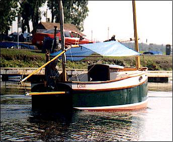
My MICRO was launched 2 weeks prior to the WOODENBOAT SHOW in Newport, Rhode Island 1993
where, on behalf of COMMON SENSE DESIGNS, it was on display. During the show, Phil
Bolger(the boat's designer) was kind enough to pay a visit. He was most impressed and left
"exquisitely pleased with LESTAT". ln talking with Mr.Bolger, he confessed that
this was the first time he had ever seen a MICRO in the flesh and approved of the small
modifications I had made to the boat. |
| As you perhaps already know, the MICRO was
designed to be an "inexpensive and simple boat that anyone could build".
Furthermore, it was to be a good sailer without taxing the crew. To that end, Mr. Bolger
designed a boat built entirely of 1/4 inch plywood, some framing stock, nails, scrap lead
and not much more. |
|
| When I first saw the study plans for the MICRO, I was smitten.
In my mind, I could see this little boat as a micro-yacht and set out to build it as such.
My desire to build my MICRO this way was informed by the following: |
1)Prior to building, I had gone to look at two different MICROs that were for sale at the
time. They appeared rather rough and flimsy with the plywood all checked. |
2)Bernie Wolfard, then owner of COMMON SENSE DESIGNS, admitted to me that after two
seasons, the bottom of his MICRO had rotted out. He also mentioned the
"softness" of the deck and some"oil-canning" with the hull. |
3)This was to be my third solo boat building effort and I knew that it would probably take
me just as long to build a "simple and inexpensive" boat with a limited life
span as it would a, more robust,long lived,micro-yacht.So I put a bit more into her! |
My MICRO, while dimensionally accurate with the plans, was therefore beefed up
substantially over the scantlings called out for by Mr.Bolger. Same notable changes are as
follows:
|
| Part |
Per Plan |
As built |
| Hull |
1/4 inch plywood throughout including deck, cockpit
and bulkheads. |
l/2 plywood for bottom,transoms(fore and
aft),bulkheads and 3/8 inch for deck and cockpit. |
| Keel |
lead slab sandwiched between two 1/4 inch sheets of
plywood and nailed to an external keel batten.Free flooding voids,fore and aft. |
poured lead keel fastened through mahogany keelson
with stainless steel rod.laminated 2X2 mahogany deadwood,fore and aft. |
| Rudder |
hollow 1/4 inch plywood shape fastened to wooden
rudder post. |
solid tapered plywood with stainless steel rudder
post and custom stainless steel tiller head. |
| Companion Hatch Rails |
1/4 inch plywood with 3/4 X 3/4 inch cleats. |
l-1/4 inch mahogany capped with brass strapping,per
BUD MACKINTOSH. |
| Cabin/Deck Support |
two rails running fore and aft. |
three full width laminated mahogany deck beams. |
Premium grade materials were used throughout with the hull fastened with stainless steel
screws (marine) and all surfaces and joints sealed with epoxy. Also, unlike what was
called for in the plans, all my plywood panels were scarfed....no butt-straps. Prior to
painting, all exterior surfaces were further sealed with 4 coats of epoxy sealer followed
by 3 coats of INTERLUX BARRIER COAT.The following pictures highlight the first stages
in my building process. Enjoy!
|
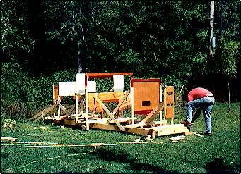
| Picture # 1, A lovely view of my father's
garage, AKA PETER'S BOAT SHOP. It was here that all the bulkheads were built, gradually,
over the course of a winter. |
|
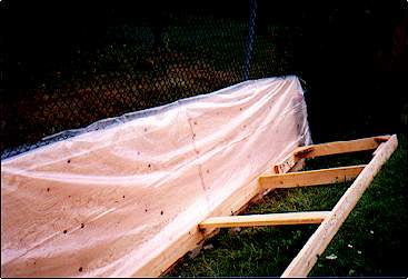 |
Picture # 2, The side panels for the hull, all
scarfed together and resting peacefully beside my "scarfing table", which I had
to build by this time since my father wished to regain use of the boat shop - oooops! -
rather, his garage! |
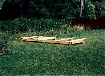
| Picture # 3, The solo boat builder's ex-scarfing
table,now set up all level and square, to be used as a strongback for setting up the
bulkheads. This particular method is most useful in allowing the builder to work at a
reasonable pace, over a period of time, without ending up with a slightly crooked hull or
being obliged to rely on too many beer-guzzling friends to help hold, glue, screw or pull
things for you. Highly recommended! |
|
 |
Picture # 4, Where's the WORK-MATE when you need
it! The six stations (bulkheads and transoms) all set up, up-side down and getting a final
bracing to ensure that they all remain true and square with their neighbors. |
| Picture # 5, SOUP'S ON!! Here we can see the basic
set up I used for boiling the water which had to be used to persuade the chine
logs............ |

|
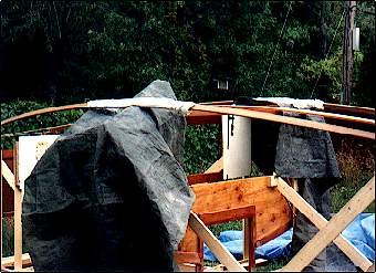 |
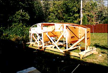
Picture # 6, Since I had chosen to beef up the
chine logs from the prescribed 3/4 X 1 to 3/4 x 1-1/2, the compound curve they had to
follow was simply too much for the mahogany. Here we can see the chine logs wrapped in
towels at the toughest part of the bend. |
| The green plastic tarps were used to protect the rest of the
structure from being soaked with the boiling water. Just barely visible, to the
left, is a Spanish Windlass which was gradually tightened to draw the two chine logs
inward, toward the centerline. Not visible, is the weight suspended from the center of the
windlass to pull the chines down into their respective mortises situated in both of the
transoms framing stock. The entire process consumed one lazy, overcast afternoon and an
odd number of cool beers. |
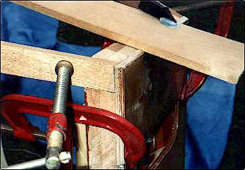
| Picture # 7, The boatbuilders best friend, clamps!
This is a close-up of the port chine log, finally clamped into its mortise and
waiting for some epoxy and a good screw. Also visible, is the forward end of the keelson,
temporarily clamped down into position to help it "remember" the bend it will
soon assume for the rest of its life. |
|
| Incidentally, at this point I had
already decided on how the keel was going to be built (traditional construction) and thus
required the presence of a keelson to receive the keel bolts. |
 |
Picture # 8, Ahhhhh.....there is nothing quite like
it! Two nasty little critters, AKA, chine logs, epoxied and screwed into their places. |
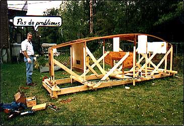
| Picture # 9, A warm and sunny day! The starboard
panel installed. The benefits of the strongback really became apparent here as I was able
to "offer up" the entire side, put a few clamps on it,and then proceed at
leisure to trace out the profile along with the location of each bulkhead. |
|
| Once this operation was completed, the panel was then taken
down, cut to within 1/8" of the previously traced profile and pilot holes drilled for
the bulkheads. This was then followed by applying epoxy onto the frames and chine
log,offering up the panel one more time and screwing,with confidence, through the panel
and on into the framing stock of the bulkheads. |
 |
Picture # l0, Later on the same day, but working in
a lengthening shadow, the port panel was also installed in the same fashion as its evil
twin, starboard panel. |
| Picture # 11, Frustrated builder, after having been
told to "cut it out and come to supper!". Ain't it always the case and just when
you think "nothin' can stop me now"! |
 |
As to the installation of the bottom, begin by using a straight edge laid athwartships and
dress down the chine logs/hull sides until everything is true and flush. Then, as with the
side panels, lay each sheet of plywood onto the bottom and trace a line outlining the
outside edge of the hull along with the location of any bulkheads crossing the bottom.
Remove the plywood panel, cut to the line and drill all the pilot holes. Follow up with
epoxy on chine logs and bulkheads, then lay your bottom panel back on the boat and screw
it down. Proceed in a similar fashion until the bottom is all closed up.For my bottom, instead of using butt-straps to join the bottom panels, l
opted for a slight variation on the same theme. See drawing below. I call it a butt scarf. |
Alright, I'll confess that all this explanation could have been
passed up simply by showing a few pictures but I do not have any, hence this cheap ploy!
But it really is as simple as it sounds!! Honest!!
|
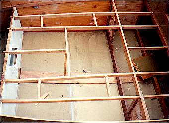 |
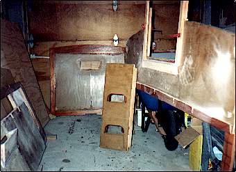
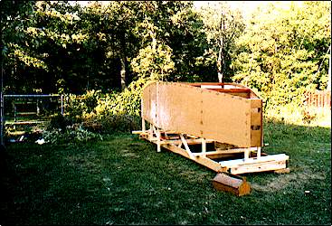
Picture # 12, With the bottomed now installed, the
boat was rolled over (2 guys, 2 beers, 5 minutes), and it was time to begin framing out
the cockpit. Here we can see the after-most bulkhead with air-vent, keelson and the
extant of the cockpit framing stock of 3/4 x 2 inch mahogany. |
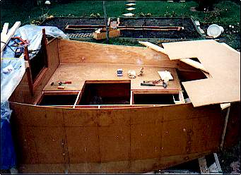
| Picture # 13, 0ne half of the cockpit deck
installed. Note the unfaired scarf at the aft end, under the as yet installed other half
of the cockpit deck. Since the scarf in the middle of the boat ate up 4 1/2 inches of
overall length, this had to be added back on.....somewhere! For those builders with time
to spare, I highly recommend making 12 to 1 scarfs in 3/8 inch plywood. Truly a great
builder of character! |
|
 |
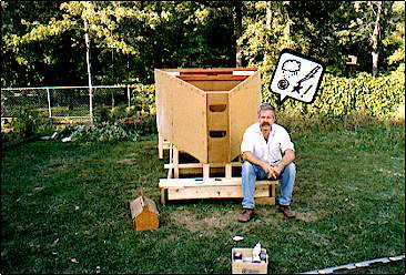
Picture # 14, Hard at work contemplating the next
step while enjoying a somewhat limited view from the comfort of a dry and very stiff
cockpit. |

|