|
Wee Lass
by Al Meyer
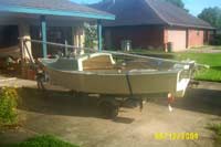
I blame this all on my father. A few years ago, I’d built a six-hour canoe. It’s about as simple a thing as you can build and still call it a boat, but it’s great for one person paddling around the local bayous. Then Dad offered to “give” me a sailboat he had; he’d bought it from a former renter and didn’t use it that often. The boat was in good shape, as were the sails, but the trailer was a different story. No license plate, no lights, u-bolts needed to be replaced, as did the winch strap, bunks and later on the leaf springs. The boat hull looked like a hard-chined Cape Cod catboat, vee-bottomed, with a beam of about half the length and a small but useless cuddy. It was called a Cardinal, manufactured by Regatta Plastics out of Houston, I suspect some time ago. When I got the boat it had no HIN and the lines were cotton braid, so I’m guessing it was built in the early 70s or earlier.
It was Marconi sloop rigged in the conventional manner, had a functional centerboard and a kick-up rudder. Combined sail area was 75 square feet
(click images to enlarge)
|
 |
|
Still, it was a good boat to train on. It was Marconi sloop rigged in the conventional manner, had a functional centerboard and a kick-up rudder. Combined sail area was 75 square feet. I spent two seasons trying to learn to sail it. It had some faults, though. The sloop rig may be the norm, but I thought it was a pain to rig. Step the mast, attach the forestay and the shrouds, attach the boom, bend both sails, and run the mainsheet. Also hook up the trolling motor. My practice at the time was to bend the sails, but not raise them at the dock. Motor out with the trolling motor about 50 yards from the dock, then raise canvas, the idea being that I’ve got more control near the dock under motor power then under sail. Coming in to dock is just the reverse.
In addition to taking too long to rig, the boat was just plain butt ugly. With a gaff rig and a barn door rudder, the boat would look very similar to a catboat, but that hull with a sloop rig just didn’t look right. Replacing the rudder would be easy. I thought about re-rigging the boat, but that would require moving the mast forward, which meant some major structural work. It just wasn’t worth the effort. Finally, the sail area was too small for light air, and too much for a good blow. The main did not have any reefing points. I tried reducing sail area by dropping the jib, but handling got on the squirrelly side.
The only decent thing to do was to build a new boat. I knew going in that building a sailboat was going to involve some serious time and effort, and Dad’s advice was “if you’re going to build a boat, build a pretty one.” I’m not a fast builder (the six-hour canoe took me three months), so the advice seemed to make sense. I started looking around at various designs, and fell in love with the Whitehall. If there’s a prize for sexiest small boat, the Whitehall would win it. Despite it’s good looks, the Whitehall has some drawbacks. According to the late John Gardner, most original whitehalls were carvel planked. Some of the more recent ones are lapstrake planked (see for example, the book “Building Catherine” by Richard Kolin). Traditional construction, either carvel or lapstrake, is not beginner-friendly. The planks have to fit just right. And the thought of steam-bending all those frames scared the bejeezus out of me. The Whitehall has another drawback, in that it was originally intended for pulling, not sailing. There’s a number of pictures showing whitehalls with sails, mostly spritsails, but this boat is really intended for rowing. That suggested to me that it would be tender under anything but the gentlest breeze. Not a good thing for someone still learning to sail.
Gradually my list of criteria was becoming more defined. It went something like the following:
- Needs to be a good sailor. I’m not looking for high performance, but for more for messing about. But it needs to be relatively forgiving for a tyro. A tippy or a sensitive boat won’t do.
- Needs to be relatively simple to build. I built stick-and-tissue model airplanes as a kid, and enjoy building, but I’m a newcomer at boatbuilding.
- The boat needs to be small enough so that I can build it in a one-car garage, and store it in the garage. Let the truck stay outside on the driveway, but I’m not going to spend the time and effort to build a wooden boat and then leave it outside.
- Needs to be big enough for me and my wife, but small enough to single-hand easily.
- It’s gotta look good!
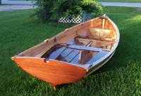
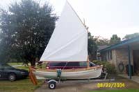
I don’t remember who, but someone suggested the Penobscot 14 by Arch Davis. A visit to his web site had me pretty well hooked, but I ordered the study plans almost as a formality. Judging from postings on the Wooden Boat Forum, and the number of completed boats shown on Arch Davis’ web site, this is a popular design. And it should be. Here was a boat that was designed for sailing, had a lot of the Whitehall influence I so admired, but the construction method reminded me a lot of the model airplanes I used to build. This would be the boat.
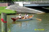
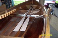
To jump to the end of the story, the boat turned out to be everything I wanted. The plans and instructions are extremely detailed, and written for the beginner. The lines of the boat are sweet. That’s not only my opinion, but also the result of many compliment’s I’ve received since I launched it. I was originally concerned that with the round-bottom hull, it might be a little more tippy than I was used to, so I built a set of oars and decide to row it first until I could get used to the hull, then sail it. Besides, I figured I could build a pair of oars faster than a sail rig, and get in the water that much sooner. As it turns out, I’ve rowed it quite a bit. The boat rows very easily, and my concerns about tippiness proved to be unfounded. When some inconsiderate powerboat or jet ski zips by, the boat handles the wake very well. I live about a mile from a boat ramp on one of the local bayous, and several time a week my wife and I try to take it out. It takes nothing to drop the boat in the water, and there’s a nice park about a 30-minute row from the dock. A simple supper of sandwiches and chips is enjoyed, and then row back to the dock before dark. A very pleasant way to take the edge off a hard day at work.
|
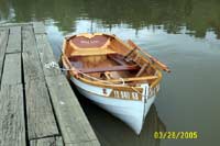
Launch Day. Although the rudder isn’t normally used when rowing, we tried it out on launch day. It’s surprisingly effective, even under the slow speed of oars |
|
At the dock, ready for a row
|
 |
|
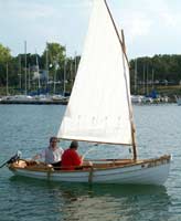
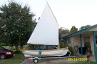
The boat also seems to sail very nicely. I’m still on the learning curve, but more experienced folks who have sailed it say that it handles nicely. Maximum capacity for sailing seems to be two adults and one child; more than that and it’s going to start getting crowded. At the Magnolia Beach messabout I soloed for the first time, and it handled great. Despite it’s traditional rig, the boat points moderately well into the wind. I’m still learning to sail under a reefed sail, but so far have handled it under a 12 knot wind with full sail and it wasn’t uncomfortable. To say that I’m pleased with the boat would be an understatement.
|
First sail. I’m showing off my ignorance here, the fenders are dragging the water and the halyard should be coiled. That damn trolling motor is also dragging the water |
|
I’m often asked how long it took me to build the boat. Time is perhaps the biggest variable; in his study plans Arch states that this is “a manageable winter’s project.” A builder in Washington State recently launched a Penobscot 14; he states that it took him right at a year for construction. As for me, I started the project in mid-December 2002, launched in June 2003, and took her on it’s first sail the following September. But by my own admission, I’m a slow builder. I also made a number of minor changes to the design, all of which increased the building time rather than shorten it. For instance, I saw a boat with some laminated thwart knees, and liked the look. The design calls for knees sawn out of solid stock. The laminated knees took considerably more time to fabricate than those made from solid stock, but in my mind were worth the effort. But be forewarned – the instructions and plans are excellent, and you don’t need any special skills to build this lovely craft, but you will need a good dose of patience.
The plans and instructions are very complete. Arch Davis also sells a video on how to build the boat, which I didn’t order. I can only watch a video so many times, and generally the wife has the remote anyway. I will try to cover any areas I had difficulty with, and give some “lessons learned” on things I’d change if I were doing it over again. Like any homebuilt, I had to make some changes, and thought I’d go over them. Making changes to a design is a touchy subject. Naturally, the designer would prefer that you build it exactly as drawn. This greatly reduces the risk that the finished product will perform as intended. I’m not a naval architect, but I am an engineer, and I can see that adding a foot of length, increasing the beam by six inches, or moving the mast forward could drastically impact all the forces acting on the boat, with the end result that what started out as a good design could end up as a dog. On the other hand, the builder/owner often takes the “it’s my boat” attitude, and to some extent, this is entirely reasonable. If I wanted a look-alike boat, I’d order one factory made. But this is my boat, something I spent my time and effort in building, and within reason, I should be able to make it uniquely mine. In all the changes I made, I was careful to follow three rules:
-
Don’t change the hull shape or anything that will affect the various forces acting on the boat.
-
Don’t make any structural changes to the boat.
-
Don’t make any changes to the designer’s intent.
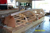
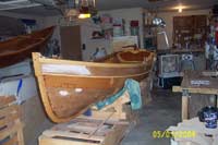
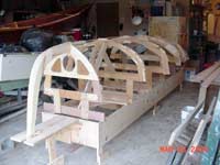
Setting Up.
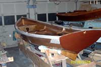
The hull is constructed upside down on a strongback, with temporary frames, two bulkheads, the backbone, and stringers forming the skeleton for the planking. All the patterns are provided full size on a sheet of mylar, so you don’t have to worry about any lofting. For the stem and transom frame I used white pine, as it was relatively cheap, available at any of the “big box” home improvement centers, and easy to work. This was probably a mistake, as I had to use Douglas fir for the stringers and keelson, and with the advantage of hindsight, it would have been nice if the stem and transom frame matched the stingers. The stringers and keelson have to take some pretty substantial bends, and therefore need to be made of stock that is clear and straight-grained. You generally won’t find lumber of that quality at the “big box”, so I went to a small locally owned store that had some good Douglas fir. The material proved to be a good choice; I would later use it for making the oars, mast, yard and boom. The temporary frames can be made from any junk lumber, as long as it’s reasonably straight in the short lengths needed to make up the frames. The bulkheads have a plywood facing with solid stock framing. The framing doesn’t show so it was made of white pine.
Frames and stem mounted on the building jig
|
 |
|
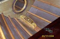
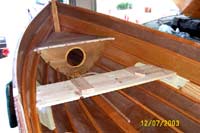
Right away I ran into one of the few serious gripes I had about the design. The forward and aft bulkheads are used to form floatation compartments. Plastic access covers are called for at each bulkhead, which when removed allows air circulation to the compartments when the boat is not in use. Given the warm humid climate here on the Gulf Coast, allowing air circulation seemed like a very wise idea, but I cringed at the idea of those white plastic covers on a wooden boat. I borrowed an idea from Iain Oughtred’s “Clinker Boatbuilding Manual” and substituted covers made of wood. They certainly look a lot better, but I’m still concerned how exactly how “watertight” they are. I’ve also since determined that my rear floatation compartment has a leak! Not enough to cause any great concern, but a little disconcerting nonetheless. If I were going to build the boat over again, I think I’d leave the bulkheads solid, and make the decks removable. Buoyancy bags or other floatation aids would be stuffed into the compartment, but the removable decks would allow the aids to be removed when not in use and also allow easy cleanup.
|
Forward bulkhead with access cover |
|
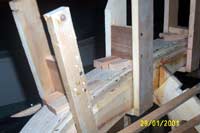
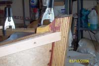
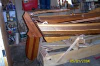
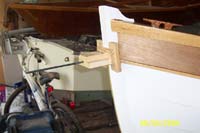
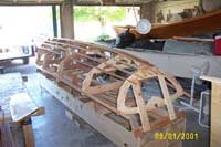
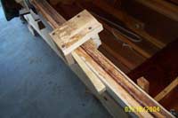
Once the frames and stem are made, setting up on the jig goes together very quickly. When constructing the frames and the bulkheads, mark but do not cut the location of the notches for the stringers. Notches will need to be cut in the transom frame and the two permanent bulkheads. The notches should not be cut until the stringers are installed, because the notches are not square. The stringers and the shear clamp will all require some pretty serious bending, so use good stock. One area where I ran into trouble was the transom frame. The stringer for the garboard planks not only takes a serious bend but also a pretty severe twist. The stringer was able to take the twist, but the transom frame, made from white pine, split when I pushed it into the notch. I solved this problem by adding a plywood doubler to the frame. The top of the doubler is below the rear seat, so it doesn’t show.
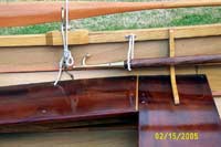
Keelson and some of the stringers installed. The date on the picture is incorrect
|
 |
|
After all the stringers are installed, the transom is glued to the transom frame. The plans call for the transom to be made of ¼” ply, but an option is shown if you want to install a small outboard motor. In this instance, three layers of ply are glued together, and a notch cut in the transom for the motor to sit. The notch is cut in such a manner that the piece left over has a sort of tongue and groove joint, so that it can be replaced when the outboard is not in use; i.e., when sailing.
I didn’t have any intentions of mounting an outboard, but I did plan on using a trolling motor mounted off to one side of the rudder. Hence I didn’t need to cut a notch for the motor but I did need the extra thickness in the transom. Rather than glue three piece of ply together, I chose to use ¾” solid stock mahagony. Using solid stock also had a benefit that I didn’t realize until later. All the plywood edges are called to be covered with a cap. I didn’t want any screws showing in the cap, but on the transom edge I never could figure out a way to clamp the cap on. By using solid stock for both the transom frame and the transom, I was able to delete the cap at this location, since there was no plywood edge to cover.
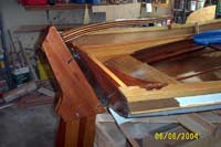
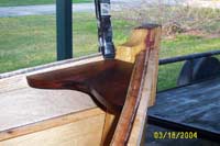
After the transom and stringers are installed, the stem facing is made. The stem facing is made of several laminates epoxied together. For resistance to dings, I chose ash for the stem facing. I first tried cold bending the laminates and was immediately rewarded by having two planks snap. I don’t have a setup for steaming, so the laminates spent some time in the shower before bending. How to hold the laminates in place was another issue. Rather than buy a bunch of clamps, I used some homemade substitutes, which seemed to work well. I made some “boxes” out of 1x4 pine which enclosed the inner stem and stem facing laminates. Wood wedges provided the clamping pressure. With a cordless screwdriver and drywall screws, they took just a few minutes to make, and did the job. When laminating, I soaked the wood, then clamped the laminates in place and let it set for about a week to be sure the wood was dry and hopefully set up a “memory.” The unit was then disassembled, the laminates buttered with epoxy, and clamped in place again with wax paper between the inner laminate and the stem. Let cure for at least a week, then remove the facing and set aside. It’s a good idea to screw a brace across the facing so that it doesn’t spring back.
|
Homemade clamps used to hold the stem facing laminates in place |
|
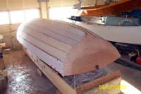
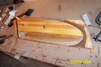
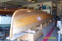
Planking the boat is relatively easy. The stringers define the shape of each plank, so spiling the shape of the planks is already defined for you. Because the planks are screwed and glued permanently to the stringers, you don’t need a ton of clamps. Due to the length of the boat, you’ll need to scarf each plank, since plywood only comes in 8’ lengths, but you can spile one half of the plank, hang it on the boat, spile the other half, and glue them on individually. This is much simpler than scarfing the plank on the bench, then having to man-handle one very long unwieldy plank. The instructions call for using occume plywood for the planks, which carried a dear price tag, but after talking to the designer, he recommended meranti plywood which was much cheaper. The lower strakes, especially the garboard, take some serious bends, but I was able to make the bends without steaming or wetting the plywood.
|
All planked. It’s hard to tell from the photo, but this boat has more curves than Halle Berry! |
|
Once the planking is done, the stem facing is temporarily mounted to the bow, and beveled to it’s final shape
|
 |
|
The laminated ash facing is hard to work without a sharp blade. The keel is then spiled, and both the facing and keel are epoxied and screwed to the hull. The entire hull is then given two coats of epoxy sealant, and then you’re ready for Turnover Day!
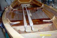
When the boat is turned, it would be a good idea to take some toothpicks and plug the screw holes from where the stringers were screwed into the temporary frames. I didn’t, and wish I had. It’s a little detail, but it makes a difference if you’re looking for such things. The interior is then cleaned and sanded, and given two coats of sealant.
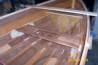
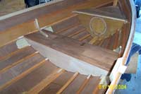
|
The fore and aft benches are installed next |
|
These are made from ¼” ply. I was concerned about the span of the aft bench; it seemed a little wide to support me or my wife (neither of us are very light). To provide an additional comfort factor, I added three risers glued from the transom frame to the bulkhead frame, then glued the bench to that. I also erred in that I should have bought some veneered plywood to match the mahogany I used for the thwarts and side benches. Finally, as noted above, it might have been a good idea to make the benches removable and stuff the compartments with floatation aids, rather than depend on a “watertight” compartment. In the photo above, the plywood doubler on the transom frame can also be seen.
The forward bench and trim piece are also installed
|
 |
|
The instructions give good instruction on how to spile the funny shapes required for the benches. After the decks are installed, it’s time to work on the thwarts and side benches. I was able to get some very nice mahagony for these pieces. The thwarts and benches have some really screwy angles, so it seemed like a good idea to make some temporary pieces out of shelf pine to make sure I got the angles right. Don’t want to mess up expensive wood! I also followed the designer’s recommendation that floatation compartments should be used as floatation compartments and not as stowage lockers, but did want some sort of locker. The design shows three different sail rigs: a gunter sloop, an unboomed spritsail, and a loose-footed standing lug. The mast partner for the gunter rig is the rear edge of the forward thwart. However, I was going with the lug rig, which had a separate partner and a mast step at the stem. Since I didn’t need the thwart to act as a partner, I took advantage of that and built a stowage locker at this thwart by adding a door on the thwart and bulkheads either side of the thwart. It worked well.
|
Permanent forward thwart is fabricated, and framed for an access door for the stowage locker |
|
Bulkheads are spiled either side of the thwart, with limber holes at the stringer locations
|
 |
|
. The design calls for the thwart knees to be sawn from solid stock, but I had seen some pictures of knees that were either laminated or steam bent. Steaming was not an option, but I was willing to try laminated knees. A plywood template was first made to make sure the angles were right. The template was then traced onto a piece of ¾” pine, and then ends extended just to be on the safe side. The pine was then cut out, making a male and female mold which was screwed to another piece of pine. For each knee, five pieces of 1/8” thick ash was first boiled, then driven into the mold. As in the stem facing, let the wood dry for about a week, then disassemble and epoxy together. A lot of work, but worth the effort.
|
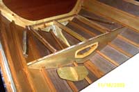
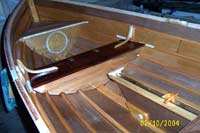
For sailing, the plans show the option of either a daggerboard or a centerboard |
|
. The daggerboard is simpler to build and takes up less space, but there are some shallow oyster reefs in the area where I sail and I was concerned that if I “found” a shallow reef, all the force of impact would be transmitted to the hull. The centerboard seemed a much safer option. For the board itself, I built the leading edge out of red oak for wear resistance, then used white pine for the remainder. The board was then fiberglassed, and then used as a template for the centerboard trunk.
Dry-fitting the centerboard trunk. The cleat was originally installed to tie off the centerboard; it will later be replaced with a better idea. The laminated thwart knees came out looking nice
|
 |
|
|
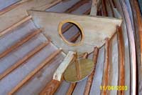
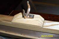
The drawings call for a mortise to be bored into the stem for the mast step, with a drain hole |
|
This seemed troublesome, as I was fairly certain that the drain hole probably wouldn’t be drilled at exactly the right location. I was also worried about wearing the edges of the mortise, since I used white pine for the stem. A separate mast stem made of red oak, with a dado milled along the bottom edge, answered my concerns.
I had some mahogany left over from the thwarts and side benches, and decided to use it for the breasthook and the quarter knees
|
 |
|
The instructions call for the breasthook and quarter knees to be installed flush with the shear, then covered with a cap. With such nice wood, I decided to show these pieces off, so the breasthook and knees were installed flush with the bottom of the shear clamp and left without a cap. The quarter knees were installed in the same manner.
|
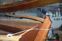
The outwales are specified to be ¾” thick by 1-1/4” high |
|
For wear resistance, I wanted to use ash, but was pretty certain I couldn’t get ash that thick to follow the shear without steam bending. I got around the problem by milling some Douglas fir ½” thick, gluing and screwing that onto the shear, then adding a ¼” cap of ash over the fir.
I didn’t want any screw holes showing in the outer layer of ash, so fabricated some “c-clamps” and wedges to hold everything in place while the epoxy cured
|
 |
|
It took a lot of clamps, but they were simple to make and cheap since the lumber came from the temporary frames.
|
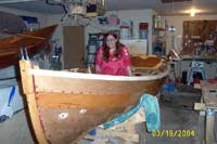
The obligatory “babe in a boat” photo |
|
'Wee Lass’ namesake, trying the boat out. Actually, RoseAnn was very understanding and supportive during the building process, and as a result, we’ve now spent a bunch of pleasant evenings rowing on the local bayou. It’s starting to look like a boat, but I’m still three months from Launch Day.
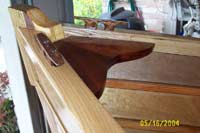
Cap rails, oar locks, and rear badge are installed
|
 |
|
The cheesy homemade c-clamps were used to install the cap rails. The rear badge is purely decorative, but is a classy touch. It will later get sealed with epoxy, along with the rest of any bare wood, prior to final finish.
|
The front badge and a rub rail on the lower edge of the shear strake installed. |
|
The rub rail is made of ash. The plans give full size patterns for the badges, so you don’t have to worry about your artistic ability in duplicating that decorative curve at the end. Prior to gluing on the front badge, I remembered that the boat would have to be registered if it were to sail (it’s just a wee bit over 14 feet), so I lengthened the badge, making it long enough to fit the registration numbers.
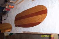
If the rudder blade is to be painted, it could just as well be made of plywood.
|
 |
|
I wanted a bright-finished blade, so gluing several thinner strips together was necessary to hopefully prevent the blade from warping. I also wanted hardwood at the leading edge for wear resistance, and at the pivot bolt location. I had some scraps of mahogany left over from the transom, so used those as filler pieces. The resulting blade came out looking very nice. Too bad the only time you see it is when it’s out of the water!
|
The rudder temporarily hung, just to check on progress (i.e., daydream). In keeping with the bright finished look, I made the cheek pieces out of solid stock rather than plywood |
|
The tiller was laminated from ash and mahogany, and is almost too gaudy.
|
 |
|
The curves are not too severe, I made a female mold of the upper curve from 2x6 stock, then cold-bent, epoxied, and clamped the layers against the mold. No steaming or soaking in hot water was needed.
|
I priced oars at the local boat store, for an 8-foot oar they wanted $75 each! |
|
Besides being expensive, they were ugly (looked they were hacked out a log) and balanced poorly. The late R.D. Culler has a book on rowing; you can get a copy from inter-library loan. He has some definite thoughts on proper oars, most of which make sense, and provides a dimensioned drawing which I used for these. I used a ¼” thick piece of ash down the center of the oar for strength, then bought some Douglas fir and laminated it either side of the ash. Cost of the fir for both oars was about $20.
In his book, Culler recommends leaving the area between the handles and the oarlock either octagonal or square, to try and counter-balance the blade at the end of that long shaft. Makes for easier rowing
|
 |
|
|
Arch Davis shows a somewhat fancier treatment for the oarlock blocks, which would be nice if I had ready access to a bandsaw. |
|
A lot of the blocks shown in John Gardner’s design were somewhat simpler, so I went that route. It would probably look a little more professional if the oarlock socket were inlet flush with the block. To me that seemed like a good place for moisture to accumulate, so I just mounted it on top of the block. At least that’s my story. As it is, I’m starting to sense that Launch Day is getting near.
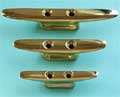
Store-bought cleats are generally either galvanized, stainless, or plastic. All probably work well, but none of them look right on this boat.
|
 |
|
I’ve also seen some bronze cleats, but they are usually too big for this small a boat. Wood cleats add a nice touch, and are easy to make. For strength, use wood with a short, preferably twisted grain.
|
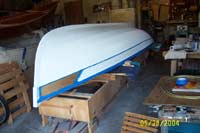
The entire interior is given two coats of varnish, as is the rear face of the transom, the two badges, rails, and rubbing strip. The boat is then hauled out for another turnover. That varnish looks good in the sunlight! |
|
The rubbing strip and outwales are masked. Hopefully I can keep the paint off of the badges! Two coats of primer followed by two coats of paint. One quart of each did the job.
|
 |
|
. I bought a “house brand” topsides paint at the local boat store, it was on sale. Since the boat will live on a trailer, I didn’t worry about a bottom coat, nor mess with a separate color below the waterline. Masking the waterline on a lapstrake hull is not an easy task!
|
One final turnover for some detail work. |
|
I ordered a polished bronze boweye from Jamestown Distributors. With the combined thickness of the stem and the facing, you’ll need a 6”-long shank. The hole has to be drilled perfectly square to the stem facing, which I knew I couldn’t do freehand, so I made a jig to guide the 12” drill bit. Worked like a charm.
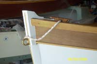
Boweye is installed, along with a half-oval bronze rubbing strip and a homemade grommet.
|
 |
|
The grommet is a nice decorative feature, and serves a purpose by providing a handy place to tie the anchor line and dock line. Since the grommet is run through the holes in the cleats, it stays put.
|
Rudder installed on it’s pintles and gudgeons. A cleat is also installed on either side near the transom; these make a handy place to run the traveler or a dock line. |
|
Launch Day finally arrived! After christening the boat with a can of beer, I take it out with my niece
|
 |
|
|
Through stumbling around on the Internet, I found an article in Duckworks by Derek Waters on how to make wood blocks. |
|
They look a lot nicer than the store-bought variety, and cost me almost nothing since I used scraps of wood I already had. I deviated from Derek’s article though in making the sheaves. Rather than turning from a solid piece of plastic, I glued two ¼” thick pieces of ash together with the grain at 90 degrees, then turned on a drill press. Hopefully that will resist splitting. The homemade blocks are a little noisier and have a little more friction than the store-bought kind, but they look great and this was never intended to be a high performance boat anyway. For simplicity, the block was simply lashed onto the boom. When making blocks, be sure to make a couple of spares – you’re sure to find a need for them.
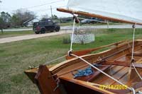
My first attempt at rigging the sail showed I needed to make some adjustments. For instance, I need to get rid of that crease.
|
 |
|
The rig is a standing lug. The sail was ordered as a kit from SailRite, but neither of my two sewing machines were able to handle the fabric, so I farmed the sewing out to a local sailmaker.
|
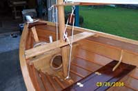
The design indicated that the boom jaw rode against a collar mounted on the mast, but several members of the Wooden Boat Forum recommended a tack downhaul for increased luff tension and better sail shape. |
|
In his book “Spritsails and Lugsails”, John Leather also shows a downhaul with a substantial purchase. Remember the “spare” blocks you made? Although not shown in the photo, later a leather sleeve was sewn around the mast where the boom jaws rub. It’s easier to replace worn leather than make a new mast.
The point where the halyard attaches to the yard was moved back. Between this and the tack downhaul, the sail shape seems much improved.
|
 |
|
|
To prevent losing the oarlocks, a “dummy cord” of tarred marlin was attached to the bottom of the oarlock and tied off to an eyebolt screwed into the stringer. |
|
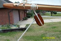
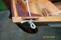
Ash was selected for it’s wear resistance for the rails and the rubbing strip, but I still hated the idea of it getting all scratched up from rubbing on the dock.
|
 |
|
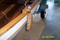
I was considering buying some plastic fenders until I saw a picture of rope fenders on the internet. I get a lot of comments on these rope fenders. They look good, they do the job, they’re easy to make, and they’re cheap! What’s not to like? Barbara Merry wrote an article on how to make them. It’s published in the March/April 1992 issue of Wooden Boat. The article gives good instructions. If you can learn how to tie a crown knot, you can make these. After three or four tries, I got it down and was able to make a fender in only a couple of hours. These are made of ½” manilla rope from the local hardware store at a cost of about $2 each. Yes, they’ll rot eventually, but at that price, I’ll just make some more.
|
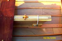
I revised the centerboard, shamelessly adopting an idea from a builder of another Arch Davis design. The waterline is only about two inches below the top of the trunk, so at any speed, water will slosh into the boat. |
|
Scott Brennecke’s idea was to build a “splash guard”. The forward and aft pieces are screwed into the trunk; the u-shaped mid section has a bevel on the front end and is held down by the shock cord. The idea is that when the centerboard runs aground, the mid section will allow the centerboard to slide forward. It works – don’t ask me how I know.
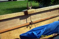
The mainsheet is about as simple as it gets. The end of the sheet is seized to a “bullseye” which runs along a rope traveler.
|
 |
|
The sheet then runs through two blocks on the boom, another block mounted on the end of the centerboard trunk, and then to the hand. I’ve heard that on small boats, it’s best not to belay the sheet. A sudden change in the wind could lead to getting very wet!
|
Again, simple is good. One end of the traveler runs through a hole in the cleat secured by a figure-8 knot, this end has a simple slip knot. |
|
Boathooks are either reasonably priced and tacky looking, or good looking but gawd-awful expensive.
|
 |
|
I order the casting for about $20, then stained a shovel handle to make a good looking, reasonable-priced boathook. Staining the handle was a bad idea. Some of the stain has already wore off.
|
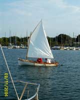
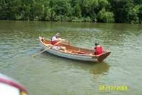
First sail. On Lake Travis, with my brother at the helm – he’s a more experienced sailor than I. Not much wind, but she sails! |
|
Due to the number of other boats at the marina, the trolling motor seemed a necessity. But it’s not nearly as crowded where I normally sail, so I’m learning to do without the motor. If things get really dicey, I can drop canvas and use the oars.
|