A while back I wrote some articles on steering options:
Well, recently I had occasion to further explore some of the options I had passed lightly over.
Steering Math Again
It occurred to me that some of the discussion of mechanical advantage in cable steering systems might have been less than intuitive. I think I have a better way. We can represent these mechanical advantages in terms of equivalent tiller length. Sailors seem to have an intuitive understanding of how long a tiller should be to control a given boat and rudder. Here’s an equation (cm or inches are fine, just be consistent):
Tiller length = (Hand Travel / 2) / .57735
The only other information we need to know is how far we move our hand to cover the full rudder travel (30 degrees to each side). This is simple with a stick, since it’s a vertical tiller. With a wheel you multiply the circumference where you hold it by the number of turns. Everything else is transparently included in this comparison.
On my Bolger light schooner, the wheel covers 17.5 feet of side travel – a tiller about 15 feet long!! It is easy to see that this is more than twice the leverage of the six foot tiller we might expect on such a boat. But that six foot tiller would require almost seven feet of side travel – inconvenient. Worse, I’ve read that in strong winds a 6’ tiller can still pull pretty hard.
So now can also see why a handle tied to the steering line about pulled my arm off – the equivalent tiller length is a meager 19”. A Norse tiller could get us to about the same and dual monkey sticks could give us around 29” – still not enough. The light schooner has a really big rudder with no balance area at all, so it’s hard to put a long enough tiller on one of these boats without resorting to a wheel.
Speaking of wheels…
Wheels for Sailboats
In sailboats and slowish powerboats most of us seem to want a traditional-looking open-spoked “ship’s wheel”. This is probably fine in a powerboat, though a monkey stick does the same job with less gear (more on that below).
In a small sailboat, however, I have come to hate open-spoked wheels. Those spokes excel at grabbing lines and winding them around the shaft, usually just when you really don’t want them to. It took a while to hammer this through my thick skull, but there’s a reason that destroyer-style wheels have mostly displaced the old style. The outer rim of the destroyer wheel sheds lines, which is a big deal on a small sailboat.
Destroyer wheels are available pretty cheaply on Ebay, but these need a 3/4” tapered shaft with a keyway. A real taper cannot be faked with low tech tools – you need a lathe and the ability to use it. I was tempted to file an approximate taper on some stainless rod, then epoxy the wheel on and lock it in place with a pin through hub and shaft. But I decided that my low-tech flange mounting system is stronger and simpler. Besides, a wood wheel feels good in the hand.
Building a decent wooden wheel is a bit daunting, but I think I’ve simplified it Ages ago in my article on metalwork I mentioned the shaving horse I built to make a banjo. Well, here’s the third banjo. (It’s the same kind of addiction as boatbuilding, so don’t get started.)
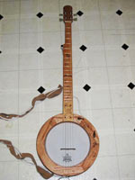 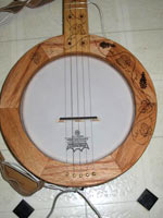 
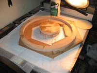
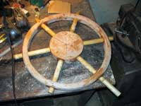
This seems thoroughly off-topic, but it’s not. Notice how the oak is joined in six “pie slice” segments? Those are simple rubbed-in (no clamping) joints with TiteBond III. The wood is cut to 30-degree miters so it fits together in a hexagon pattern. After gluing it is cut to shape and planed or sanded flat. Join two layers of this with offset joints and you have a pretty strong assembly. Add dowels and it’s really strong. Because I’d built these round banjo parts that way, the technique leapt to mind for steering wheel parts.
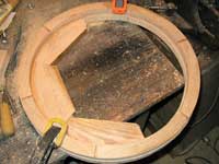
The hub and rim are two layers of ¾” red oak scrap, and the spokes are 7/8” dowel rod. If you can cut an accurate 30 degree miter, the joints are pretty easy. If not, you’ll be doing some sanding to fit like I did. Here are the layers of the rim being glued up, then the excess being cut away.
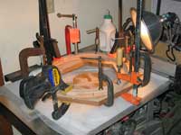
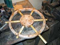
I rounded the edges of the rim with a ½” roundover bit on the router, then I glued the spokes in with thickened epoxy. Since my doweling was noticeably smaller than my nearest drill bit, I couldn’t make it fit tight enough for Titebond III. It was a giant mess getting the parts tapped into place with gobs of epoxy everywhere, but I couldn’t think of a neater way to do it. Make sure you wipe up all the squeeze-out or you’ll be stuck sanding it! It helps to scrape off any you missed when it’s at the rubbery stage of cure.
Once everything was glued in place, I bored through the hub and rim at each spoke to glue in a dowel, locking the spokes in place. I also dowelled the layers together between spokes. It might not be necessary, but I doubt it hurts either. I also think the dowels also look nice too when finished, distracting from the router errors I didn’t want to bother sanding out.
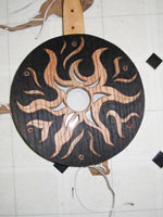
With all the dowels cut flush and everything sanded, all it needed was finish. I like Thompson’s Water Seal these days, as it goes on easy and cures fast. I guess time will tell if it’s really any good. After that it was ready to bolt to the flange.
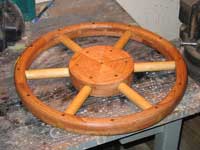 
The copper plate is something I made by slitting and flattening a scrap of plumping pipe, then polishing it up and hammer dressing it. It is there to spread the load of the bolt heads and hide my imperfect center joint. I tried using painted steel first, but it just didn’t look right with oak. If you’re going to try this hammer dressing thing, make sure you have some crocus cloth or a buffer to smooth the metal and the hammer’s ball before you start denting it.
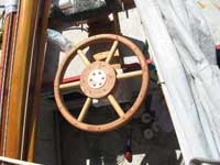
I suppose this wheel looks a bit out of place on a schooner, maybe more like it should be on a 1920s style runabout. But it’s better than gleaming stainless steel. Actually, I keep thinking it looks like a foundry pattern for a large cast iron fire valve wheel. But no matter how it looks, it certainly works much better around lines than the open-spoked wheel.
Cable Run Mods
Speaking of the steering on the schooner, you may remember the Byzantine complexity of my cable runs. When you want to have it all, you pay a price. At the time I was willing to deal with an overcomplicated system so I could have access to the port-side compartment from the rear cockpit.
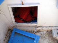
This meant taking the cables straight forward from the steering drum into the compartment, then to the top of the compartment and across to the side where they emerged again to run aft. Now I’m willing to accept fewer features for easier maintenance.
What prompted this was the failure of a sheave inside the compartment. Well, the sheave didn’t actually fail – my mounting did. It allowed this non-pivoting sheave to twist a little, allowing the cable to run off and jam between the sheave and cheek. While I was wedged under the thwart with my head and one arm through a tiny hatch, I realized that I seldom actually used that hatch. All I ever reached in for were lifejackets that could be reached from the forward cockpit. After I recovered from the contortions, I screwed it shut and moved all the cables out of the compartment.
For what it’s worth, I think I could have gotten away without that lower sheave if I’d placed the padeye a little higher. Either way, this is so much easier set up and to maintain it’s ridiculous. Actually, it highlights how ridiculous it was for me to insist on features I could do without.
The Monkey Stick
Expedience led me to revisit the monkey stick. It is a terrible line-catcher on a sailboat, but it works beautifully on a powerboat. My AF4B was pretty much ready for Rend Lake 2008, but my motor lacked a tiller. (The funny part is that I got a motor with a tiller after this was mostly set up. Isn’t that the way it goes…) I suppose it would have been simpler to buy a tiller to fit the motor, and use a tiller extension. But I don’t like having a cockpit-sweeping tiller extension, since I’m nearly always out with at least three other people. Fortunately the monkey stick is nearly as simple, which is why it used to be pretty much standard on small boats that had remote steering.
The stock tiller gives a pretty good idea how much steering power we’ll need. This motor has the center of the handle 16” from the center of the pivot – its effective tiller length. (Overall length is 18” from the pivot.) The end of the tiller moves through about 26”. As long as the head of our stick moves at least that far to cover the motor’s full travel, we should be OK for leverage.
Then we need to figure out how far the steering fitting on the motor fitting moves. This is a simple matter of lining up a tape measure with the fitting and then pivoting the motor. If you have a 1950s or 1960s OMC 10 or 18 horse motor, it’s probably 12”.
A quick scale drawing gets us close to the mark. I think a 36” stick is good, since it’s comfortable for me both sitting and standing. You’ll have to experiment to find the right height for you. The cables are most convenient to mount at around 15-16” above the cockpit sole, since that’s about the height of the motor’s cables. (Assuming the cockpit sole is the bottom of the boat.) If we attach the cable to the stick at this point, the end of the stick moves about 25”, which is perfect.
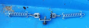
When I diagrammed the cable run I discovered a difficulty. The standard fitting OMC made for steering the motor uses two sheaves. This gives a 2:1 mechanical advantage and we need to move 18” of cable. Attaching the cable to the stick in the same place means we now move the handle about 40”, which is way too much. So we also need sheaves on the stick to keep this a 1:1 ratio. This creates a rather complicated system, as seen below left.
One fitting, seven sheaves, four springs, and two completely separate sides to the cable run. What a convoluted way to get a simple 1:1 ratio! What if we could simply attach a single set of springs to the motor’s fitting? That system is shown to the right of the other one. This gets us down to five sheaves, two springs and only one length of cable to adjust. I like the simplicity, but we need to look at some mountings.
Mounting the springs to the motor is simple. We use OMC’s adapter, but remove the sheaves and put on springs. OMC was clever enough to provide split links to make this easy. I have seen these fittings, however, with figure-eight closed links. If you have one of those, it is not hard to disassemble the springs to install them. Or of course you could cut the links off and put on any kind of split links.
Attaching the cable to the stick is not much harder. I drilled a hole and ran the cable through it, then locked it in place with two cable locks – one is the nice stainless kind from Duckworks, and the other is a more-expensive galvanized wire rope fitting from West Marine. The wire rope fitting is obviously not purpose built, and I got stuck using it solely due to poor planning on my part, but both work. With either type, a washer keeps the wood from getting chewed up. This cable clamp method seems secure enough, but if there were any doubt I would run the cable through twice and take a couple turns around the stick. So far no need.
The cable run is no different from what you’ll read in Max Wawrzyniak’s book or articles, so I won’t belabor it here. The main difference is that instead of a steering unit up front, we have only a single sheave. By the way, if you have a console-mounted compass, consider how little metal this puts near it compared to a wheel installation.
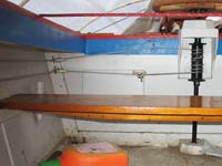
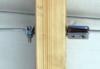
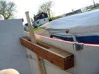
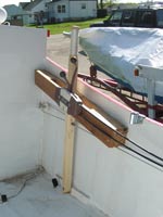
Let’s look at the brackets that hold this stick in place. The stick itself is about 1.5” square and laminated from two layers of scrap 1x pine. I used Thompson’s Water Seal for the finish, because it’s quick and I was short on time. The brackets are self-explanatory, I think. Except be sure to account for how far away from the side of the boat the cable naturally lies. That’s the best place for the stick.
I coated both stick brackets with Thompson’s Water Seal as well. I think this will be great for the top bracket, but I doubt the paint on the bottom bracket will stick for long, since Thompson’s is basically wax. I also coated the underside of the upper bracket with Vaseline to make it difficult for wasps to build nests in this attractively sheltered structure.
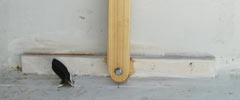
This bottom bracket is probably not the best design. It is simply a piece of 1x lumber with a T-nut fitted in back then screwed to the chine with PL400. The stick is screwed to the T-nut with a bolt and a couple washers. It would probably be better to double the outside of that joint with a piece angle iron or wood. The axle bolt would be much stronger that way, but you’d have screw holes to fill on the bottom of the boat, which I didn’t have time to deal with before the Midwest Messabout. I’ll probably get to adding that angle eventually, but in the meantime I’ll be sure not to kick it too hard. I might also be a good idea to provide the bottom of the stick with some metal side plates to prevent the end splitting out.
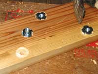
We still have to control throttle and shift. I attached the remote control box is attached to the upper stick guide…
...using T-nuts so it wouldn’t interfere with the stick.
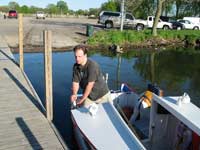
In use, the monkey stick doesn’t look as showy as a wheel, but it is every bit as handy. It is especially nice how little space it takes up. I don’t think it would be too handy for a ski boat or any other kind of acrobatics where you really need to have one hand on the steering and the other on the throttle. But for low speed maneuvering it works fine to put the left hand on the stick and keep the right on the shifter.
Rob Rohde-Szudy
Madison, Wisconsin, USA
robrohdeszudy@yahoo.com
|