| (before
your motor does)
While I was living in Madison, most of my boating was on the city’s lakes. They are not deep by the standards of mountainous regions, but plenty deep for an outboard motor to operate without worry. After moving back to Mazomanie, the closest water is now the Lower Wisconsin River. This is very shallow – much of it ankle deep unless there’s been a lot of rain. Sailing is out of the question and you need to be able to find the channel to operate an outboard motor without dragging the skeg.
The trouble is that the water is brown from the tannic acid leached from tree roots upstream. If there hasn’t been much rain it is usually possible to see the sandy bottom as it shoals to within maybe 18” of the surface. This is enough to know it’s time to take the motor out of gear. But if it has rained, the water gets even darker, and the bottom is invisible until it is ankle deep! This means the first warning of shallow water is the boat getting hard to steer because the motor is dragging.
So what to do?
Low Tech – the pole
The first thought for a lot of us will be a leadline, since it is the traditional sounding method. The problem with a line is that you have to toss it ahead and keep it taut long enough to read it, then yank it up fast before it fouls the prop. That is far more exciting that I like.
A pole is simpler to use in water this shallow. We just poke around, feeling the bottom like a blind man uses his cane. The pole is always straight, so we get a much more instantaneous depth reading.
In water like this you’ll want a pole anyway, since the motor can’t get you to a lot of places for lack of water to operate in. So the first thing is to mark the depth where the motor touches bottom. This is easily done by literally dragging the boat to where the motor touches bottom, and marking the stick.
You have now turned your pushpole into a dual-purpose sounding pole. This works best with someone in the bow operating the pole, obviously. If I need to do this solo, I actually like a shorter, thinner stick. Literally, it is more like a walking stick, and much handier to stow on the cabintop or in the cockpit when I need it out of the way. An old ski pole might be ideal, but a scrap 1x2 works fine.
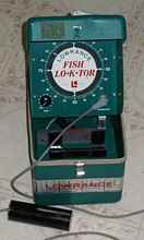
High(ish) tech – the fishfinder
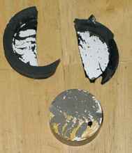
Electronics can tell us a lot more with less effort, and we don’t
even need particularly modern electronics. The photo below is
a Lowrance Fish Lo-K-Tor made in (I think) the late 1960s. (They
started making them in the 1950s.)
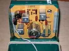
These older “flasher” fishfinders are pretty simple
sonar devices. There is a wheel driven by a small motor at a controlled
speed, and it has a xenon tube on it. It flashes whenever the
transducer in the water hears a sound at the right ultrasonic
frequency, 192 kHz in this case. Each time the wheel passes zero,
it flips a switch to send a pulse of sound at that frequency.
However far the wheel turns between the time the pulse is sent
and the time it hears the return pulse equates to the depth of
any reflective objects – the bottom, fish, weeds, etc.
Simple, eh? Even from the parts count you can see it’s
simple.
I don’t have the schematic, but I’m guessing we’re
looking at a crystal oscillator that generates a 192 kHz, 12 volt
signal. That frequency drives a synchronous motor (so it’s
speed controlled by the oscillator), gets sent to the transducer
by the wheel’s switch, and also feeds into a small transformer
to step up to the higher voltage needed by the xenon tube. (This
also saves cost, since the high frequency lets them get a higher
voltage with a smaller transformer. In a TV set they call this
a “flyback” transformer.) The remaining circuitry
would be an amplifier for the returned signal. This is all a guess,
but with so few parts I can’t see how they’d do it
any other way. And simple is good, so I like it!
I got the unit seen above for $10 at an estate auction, along with a rather impressive instruction manual. (This was back when they were written by people who actually spoke English and really knew fishing. This manual explains that you can test a fish finder by holding the transducer 2.5 feet above the floor – the unit should display 10 feet, since sound travels four times faster in water. (See what I mean about it being a good manual?)
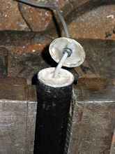
Under test, this unit worked perfectly … when it worked. The fault was something I’ve seen more times than I can remember as a musician – the wire inside the cable broke right where it enters the transducer. Copper fatigues after repeated bending, and there’s nothing anyone can do about it, short of a really bulky strain relief. I couldn’t find any position where I could tape the cable down to get reliable operation, so I wheeled the patient into the operating room.
Transducer repairs, cobbled
I haven’t found anything online about repairing these transducers – I guess most people figure it’s impossible. But I figured I’d be no worse off if I failed, so why not try? At worst we'll learn something. A transducer is like a microphone, and I’d worked on tons of those. Actually I’d guess it’s more like a stethoscope, but electrical – a metal diaphragm at the bottom, then a coil of fine copper wire surrounding a ferrite core. (Again, a guess.) So the game here is getting to some good wire without cutting into the copper windings. If we hit the windings, this becomes an impressively more complicated project, and probably not worth it.
Let’s see what we can do!
I clamped the unit in the vice (gently) and carefully hacksawed
off the metal top. This revealed epoxy potting.
Ugh. This is not going to be easy! Let’s drill through
this mess. But very slowly and carefully – if we hit the
copper, it’s probably game over.
Wow, more of this is potting than I expected. Now that I think
of it, they also made flat transducers. Most of this tube is probably
just dead space so it can easily clip into the holder! Still,
let’s not make any rash assumptions. This is enough wire
to make a splice. First we strip the outer insulation. Careful
use of a fingernail trimmer can work in such confined areas.
I guess I wasn’t careful enough! Either I’m clumsy
or it was broken further down. Well, nothing for it but to dig
further. Below the epoxy was hard rubber. I cut off some more
steel started drilling that out too.
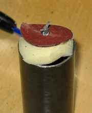
After drilling and cutting out the rubber I came to a layer of
stiff, red cardboard. It seemed to be impregnated with some sort
of plastic (probably phenolic) and was very tough. Rather like
very hard linoleum. After carefully cutting enough of the cardboard
to pull it out I hit the jackpot – a foam plug and empty
space.
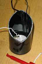
Smooth sailing from here – just re-solder the shielded
wire and test. Or not. Still intermittent! I cut off some more
steel and found that the problem was the black wire – the
one that goes under the transducer itself.
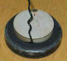
This is getting ugly. Now I’m going to have to dig
into the part that is most likely to kill this thing. Here’s
the transducer with a lot more of the steel casing cut off.
I accidentally popped off the white wire. Wow, that sure looks
like a piezo transducer. I guess that explains why the resistance
seemed so high for a coil (like 3 megaohms) – it ain’t
a coil. Well, coil or not, it won’t work unless we can get
to where the signal is failing. And that is getting harder! More
careful steel cutting.
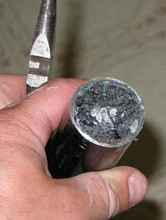
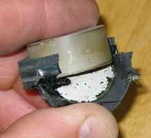
Unfortunately it wasn’t the steel that killed the transducer.
The rubber on the bottom took the metalized coating right off
the crystal.
I was sort of afraid it would do that, but now we know. We also
know that if the wire had been broken anywhere else, this repair
would have been worth pursuing! Even better, I found out that
any 192 kHz transducer will work on this unit, and Cabela’s
carries them for $50.
However, the more I think about it, the more I’m not sure this is even the right tool for the job. A fish finder—even an ancient one like this—tells you an awful lot about the bottom and what’s between you and the bottom. But it tells you a lot less when the bottom is really close to you. The readings I care the most about would be between one and two feet. On this instrument’s readout, those readings with tend to blend right into the blob of light at zero.
Since I don’t care much about the deep water, I really only need an alarm for shallow water. I bet we can make this a lot simpler.
Low tech again
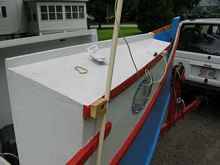
I guess what I really need is an indicator to warn me when we have less than 3” of water under the skeg. Maybe we can use the pole approach, but make it more automatic.
Here I can finally give you a use for that fishing pole you broke the tip off of, but couldn’t talk yourself into throwing away. Unfortunately, I threw my broken pole away when moving to the new shop, so I had to use ½” CPVC pipe. The only other things we need are some rubber bands, some scrap solid wire, four screws, a screweye, some light line, and a spring clamp. (What a great cliffhanger, eh? If this were television, I’d now say, “When we come back, see how we put it all together!” You can simulate this experience by clicking on a few of Chuck’s advertiser links now. Go ahead. I’ll wait. OK, now back to the show.)
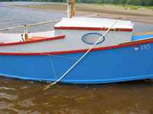
The idea here is that the lower end of the rod hits the bottom
and you can see the top end of the rod move as an indicator. This
will happen at a preset depth based on how far you make the rod
extend below the bottom of the boat.
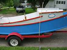
I started out by putting a screweye in the chine. This will be
the pivot point. I placed this one at the aft end of the cabin,
starboard side, so it is easy for me to see when piloting the
boat. The motor's lower unit extends 12” below the bottom.
I allowed an extra few inches and drilled a hole 16” from
the end of the CPVC pipe. I ran a scrap of line through this with
a stopper knot, then through the screweye. (Actually I used a
scrap of insulated stranded 18 ga wire, but any light line would
do.) The line is led through the screweye and up to the cockpit
where the spring clamp holds it to anything stationary and convenient.
I use the steering stick guide but most will probably use the
gunwale.
 |
The idea was that this clamp would serve as a “fuse”,
letting the line slip if I hit hard, but I guess I need a weaker
clamp for that to work. However a spring clamp isn't exactly adjustable,
so if you do want it to let go, a better solution would probably
be an auto-release clam cleat and fairlead. However, the CPVC
is flexible enough that it doesn't seem to matter much.
By the way, it is not a bad idea to make the lower line rather
long and tie it to something, so you don’t need to re-thread
it when it yanks out. I didn't do that on the prototype, but I
will when I make it more permanent.
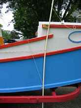
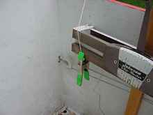
We then need a guide to keep the top of the rod against the side
of the boat. This is a simple matter of some wire, scrap 1x2 and
screws. I turned a loop in each end of the wire with needlenose
pliers to screw it down. Obviously a wooden guard would look nicer
for a permanent installation, but remember it needs to curve with
the side of the boat to allow space for the pipe to move.
Note that I tied the uppermost eye to the upper guide, so I don’t
lose the rod if the line pulls out of the clamp.
Then we need a return spring. I made a chain of rubber bands (lark's head knots), and one of these loops can drop over anything convenient. The bimini bracket works nicely in my case. You want a fairly long band, as shorter bands won’t allow enough travel.
It takes a little fiddling to get the tension right on the rubber band. It needs to be tight enough that the water pressure alone doesn’t move the rod too much on plane, but obviously it needs to move when you hit something!
That’s it! I suppose a nice touch would be a bit of flagging tape on the top, to make the rod’s movements more obvious. In practice, however, you know when you hit bottom. It smacks the forward end of the upper guide and your hand had better be yanking the throttle back immediately.
Quickdraw
One issue with this setup is how little warning you get before running aground. I have about 8 feet between the “sensor” and the motor. At 5 mph I get about one second of warning between the stick touching and the motor reaching the same spot, and some of that is taken up with stick flex. I know my reflexes aren’t fast enough to kill the motor in that amount of time. At full planing speed of 15 mph this drops to about a quarter second!
Since a human response isn’t reliable, can not automate it? The easiest method would be to have the indicator stick yank out the kill switch key. It turns out this is pretty simple to rig. Just add another line and tie it to the kill switch key at the right length. This seems to work, but I haven't tested it enough to know if it's reliable.
Part of why I haven't tested it is I'm not sure it's a good idea. One has to be careful where one uses this. In water where there are dangers like barge tows or dams, I’d be reluctant to have the motor shut itself down for any reason. But I guess it's unlikely either of those dangers will be present in under two feet of water.
So there you have it, three ways to find depth before your motor
does. Now you don’t have to tie your mother in law to the
bow anymore.
Unless, of course, she didn’t read this article.
Rob Rohde-Szudy
Mazomanie, Wisconsin, USA
robrohdeszudy@yahoo.com
*****

|