|
Part 6: Finishing the hull
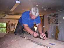
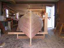
The planking is now complete. The final bits of the hull are the keel plank and the outer stems. The landings for these outer pieces need to be checked for fairness. In the case of the stems, the Stanley 113 is the ultimate tool. The adjustable bottom of this compass plane effortlessly fairs off any irregularities.
The keelson landing needs a bit more elbow grease and a regular jack plane.
Work it along out to the width of the keel plank, and make sure it stays level as you go.
Stiff battens can help identify high spots.
Now the stems. I laminated these up on the lofting floor over a year ago, and by the time I got around to using them they had sprung a bit. I probably could have fit them, but decided it would take less time to laminate replacements right on the hull. The laminates were bent and pre-fastened to the stem with sheet rock screws and plywood pads.
Glue was applied and they were fastened to the hull.
If you are prepared to do both ends at once you can save glue from the squeeze out to use on the other end.
When they are dry take them off (I coat the screws with tallow so they won't stick) and do the bevels on the bench.
The keel plank is let in at both ends and they are ready for the glue up using the same screw holes.
Then glue the keel over them (first roughing out the centerboard slot). The slot is finished with a router using the keelson slot as a guide, so make sure you get those glue drips out before it dries.
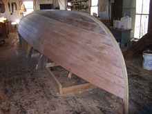
Final fairing occurs after the glue dries.
(A note on the best laid plans here: when I cut the slot in the keelson a year ago I used the outer surface of the keelson to guide for the opposite slot edge. Sounded like a good idea but in fact the keelson had a curve which, although slight, left the centerboard slot a little narrower toward the center. This had to be straightened out before the slot was of uniform width.)
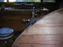
Finish
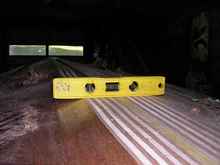
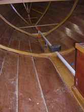
When everything is as fair as you want it, the time has come to seal. A good finish is time consuming. I pay great attention to the finish above the water line, but below it I am happy to have it a little rougher. I was not sure exactly where the load water line was on this old plan and selected the probable line, about 18" below the sheer amidship, based on photos of old boats in use. I scribed it using a jig that slides on the supports for the molds. These supports were leveled at the beginning of the set up and were more true to the hull than the floor of my shop.
The pointer rests on a shelf and can be moved back and forth as the hull widens. The frame slides on the supports and can move in and out freely as well. There is a ball point pen in the end of the pointer. It worked out pretty well (and was fast), but your eye is the final arbiter of the fairness. Now the hull is ready to seal.
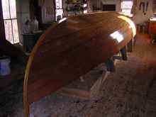
Two coats of epoxy , a final sanding, and then a final coat. The waterline shows through the finish.
I used interlux epoxy primer above the waterline with brightside paint and, below put bottom paint directly over the epoxy.
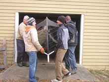
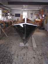
Upright
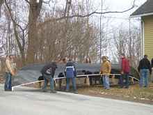
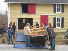
I wasn't sure how much the hull weighed at this point and got 14 people to help with the flipping. The hull lifted easily (16,17,18), came out the door, was rolled over, and put back in a few minutes.
I would guess it weighed 400 lbs. With the molds out you can now get at the glue that got under the molds . This is tedious work. The WEST people say it is safe to heat it up with a heat gun and scrape it off: chisels and scrapers help.
Bob keeps everything plumb and helps with internal measurements.
Centerboard
The trunk was made out of locust beams and 3/8 meranti ply; The rounded bottoms of the uprights fit into the slot with less work than a square section. The dimensions were scaled up from the drawings in the whaleboat plan. It is helpful to fit the centerboard and drill the pivot hole before you close up the trunk.
It was sealed inside and out with epoxy and glued in place.
The board itself is 3/4 ply with about 10# of lead inserted and a copper pipe bushing for the pivot bolt.
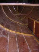
The floors
Traditional whaleboats had a ceiling (inner planking nearly to the gunwale). They also have raised floors at the ends, as the hull narrows, for more floor area. I spent about three weeks playing with sticks to get an idea of where the end floors would be (the "bow sheets and sternsheets") and to decide how much of a floor would be best amidships. I decided to follow the run of the third plank and place two floors in between every rib, 12 " apart. The actual floor boards will rest on the ribs and the floors, giving about 1 1/2 " under the boards. Each floor was made using a pattern. First, the pattern material was placed in position and scribed with a compass.
Then vertical measures were taken at each of four points (marked with blue tape) using the closest rib; remember to take the measure from the side that marks the station line, since the rib is deeper in this location.
These points are connected with a batten and a curve is cut out.
And drawn onto the floor stock, 3/4 white oak. The two sides of the boat were not exactly the same and the pattern was re-cut and then measured vertically on the stock for the opposite side.
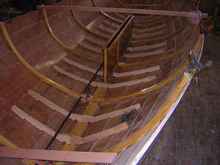
A batten along the centerline helps determine the height of the central flat area; note the spacer block on the 7th rib to make the floor wider at this frame.
Ribs 4 and 5 need wedges to bring the central flat up to the right height.
All the floors have limbers cut like the ribs. When they are all laid out and temporarily fastened with screws to the planking (at the laps to avoid going through the finished hull), you can test the fairness by placing a stiff batten atop them to look for high spots. Fine tune them, seal them and glue them in. The edges are cut back square 1" inboard of the third plank edge, where there will be a filler strip below the floorboard, riding on the lap seam.

|