| Andrew is an architect, designer of boats and SketchUp aficionado. He runs summer SketchUp training courses from his studio in South Pelion, Greece.
His boat designs are on Duckworks.
His website is here: andrewwaltersdesign.com
How to Draw a Boat Using SketchUp 3D Software
When it comes to boats and boat design, I'm a bit of a 'newbie'. I really got interested in boats when we bought a house in Greece and built my first boat here in 2008. After that, I got the bug which led me to start designing them (I'm an architect so that sort of thing is in my blood!)
I'd been using SketchUp 3D software for my architectural work. Its ability to create models in 3D and manipulate them led me to explore how it could be used to design boat hulls.
After some trial and error, I developed a method that worked and designed a boat. I emailed it to Duckworks and Chuck was kind enough to give me a page here to feature my designs.
Since then I've read a few articles on Duckworks Magazine which relate to boat design and it crossed my mind that some of you might be interested in how I go about creating a design.
This article aims to show the reader how to draw a boat in SketchUp 3D software. I hope it might be of help to those out there who have a design in their head and just can't get it on paper. The hydrodynamics are not considered here and may be the subject of a future article. In the meantime, I'll direct those interested to Marcus Bole's PolyCAD website where you can download his hull design and hydrostatic software: www.polycad.co.uk
I import my SketchUp designs into PolyCAD for hydrostatic analysis.
Please note that the subject of this article is a preliminary design for a 12' x 5' beam small skiff, created simply to show how to go through the process and give you the knowledge needed in order to make a better design for yourself!
The Software
SketchUp is available in two versions, the free version - SketchUp Make, and the professional version – SketchUp Pro. I use SketchUp Pro but everything shown here can be done with the free version – providing it is not for commercial use. You can download SketchUp here: www.sketchup.com
In addition to the free software, I make use of a few add-on pieces of software, called 'plug-ins'.
The ones used here are:
Extrude Tools by Tig
BezierSpline by Fredo 6
Let's get started!
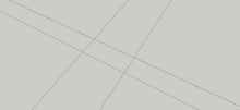 |
Use the tape command to draw a rectangle that is the length and beam of your design. |
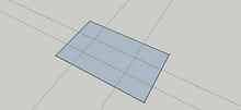 |
Draw a rectangle over it - make it larger as shown. |
|
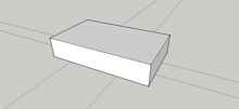
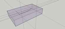
Extrude the rectangle - make the extrusion taller than the boat that you're designing. |
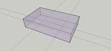 |
We're going to draw the 2D views of the boat on the sides of this box, and then extrude and intersect these lines in order to create the edge lines of the plywood panels. |
After that we'll put surfaces between the lines to make the hull panels.
Then we'll flatten the panels to form the flattened shapes of them.
At this stage I want to see inside the box so I use the paint bucket command. Create a new material, edit the colour to something you will notice, then reduce the opacity so that you can see inside. The example above has an opacity of about 20%.
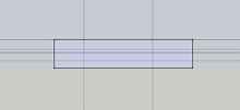
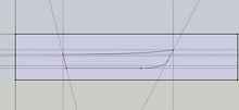
Use the view toolbar for a top view and then, in the Camera list on the top line, choose parallel projection.
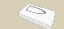
Move the tape lines from the bottom face to the top face and add another tape line centrally from bow to stern.
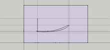
Over these tape lines, draw the transom line and the sheer line.
For the curve on the sheer line, I use Fredo's Bezier Spline Plug-in.
 |
This is a 3D view. I've now added vertical tape lines at bow and stern ends. |
 |
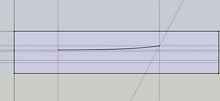
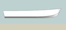
This is the side view in parallel projection. |
I've added horizontal tape lines to the face to represent the high and low points on the sheer line and the motor mounting height on the transom.
 |
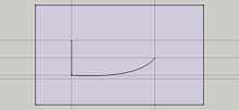
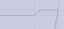
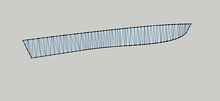
Over these lines I draw the sheer line using the BezierSpline plug-in. |
 |
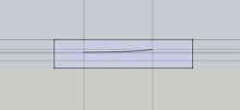
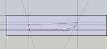
This is what we have so far. |
The transom and sheer line, as viewed from the top, and the sheer line as viewed from the side.
I've also transferred the lines on the side view and top view across to the rear (stern) view so that I can draw the transom as viewed from the bow.
 |
This is the bow view, parallel projection, with the transom drawn on the face. |
 |
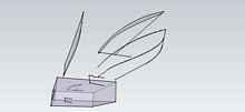
Add some curves using the Bezier Spline plug-in. |
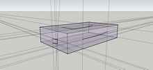 |
3D perspective view |
 |
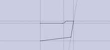
Go back to the side view, parallel projection. |
 |
Add the stem, keel and transom lines. |
 |
Then the chine lines. |
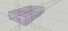 |
Now we have a cube with the lines of the boat drawn on each face. |
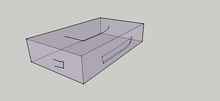 |
Same view, without the guide lines – looking less confused. |
 |
On the top face of the cube, add the chine lines. |
 |
3D view |
 |
Same view without the guide lines. |
 |
Make a copy. We're doing this so that if anything goes wrong, we'll have something to go back to. |
 |
Now we use Tig's Extrude Edges by Vector plug-in to extend the stem and keel line horizontally. |
 |
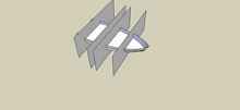
Then vertically. |
 |
Then intersect these edges. |
 |
After deleting the surfaces that you've extruded, you're left with the stem and keel line. |
 |
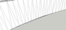
Now the sheer line. |
Using Tig's Extrude Edges by Vector plug-in, extrude the lines on plan view and side view, then intersect the edges.
 |
The result after deleting the extruded surfaces is the sheer line in its three dimensional position. |
 |
Repeat the process with the chine line. |
From this view, you see that we now have the lines of the stem and keel, the chine and the sheer.
 |
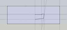
Now I take another copy so that if anything goes wrong, we'll have something to go back to. |
 |
We now need to create the transom lines. |
Again, extrude the lines, intersect, then delete the extruded faces.
 |
Like this. |
 |
This shows the top line of the transom. |
 |
Now join the intersected points to create the transom face. |
 |
I then make another copy – just in case anything goes wrong. |
 |
After deleting the unwanted geometry, this is what we have. |
The transom face and lines representing the position of the keel, stem, chine and sheer.
The next stage is to put the side and bottom surfaces on the hull, using these lines as the edges of the surfaces.
 |
First make two copies of the hull and delete unwanted geometry so that you're left with two sets of lines that form the edges of the side and bottom panels. |
 |
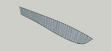
Then use the Sandbox, 'From Contours' command to create the surfaces. |
Just triple click to select everything, then click on the Sandbox, 'From Contours' command.
The above shows the faces that have been created.
 |
This is the same view showing the hidden geometry. |
Note that the curves drawn by SketchUp consist of a series of straight lines. I used the default setting here but there is an option to adjust the number of straight sections in a curve.
Note also that the Sandbox tool has created a surface by drawing lots of triangles between the curve sections.
This is useful because later on, we can use a plug-in to twist each triangle onto the same plane as the adjoining triangle. This will give us the true shape of the flattened hull panel.
 |
The Sandbox, 'From Contours' command sometimes forms an extra surface - like this. |
One needs to zoom in and delete this extra surface.
 |
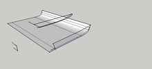
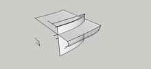
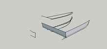
At this stage make the transom, side and hull panels into components. |
Now put the bottom and side panels onto the transom.
 |
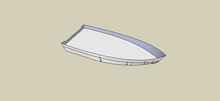
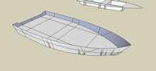
Hidden geometry not shown. We have half a boat hull. |
 |
Side view. |
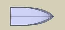 |
Plan view with the two halves joined. |
 |
We'll now add the interior. |
I'm going for a seating arrangement of abeam at bow, stern and midships. Plus side seats running bow to stern.
The vertical supports will form part of the structural framework.
First go back and make sure that all of the hull parts are components. You've probably come across 'sticky' geometry by now. Components and Groups are the way to avoid this and at the same time organise your model.
Then draw a large rectangle below the hull - and bigger than the hull.
 |
Pull it up until it's at the required height. |
 |
Select the rectangle by triple clicking it, then use the intersect faces with model command. |
Then delete everything except the surface within the hull.
Make this a component.
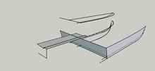
 |
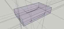
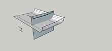
Now arrange vertical faces in the positions of the seat supports / frames. |
Same process, select all by triple clicking, intersect faces with model, delete unwanted geometry.
 |
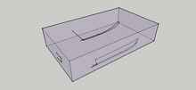
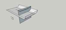
Repeat for the side seats. |
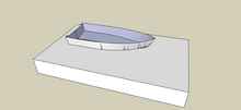
 |
The model so far. |
 |
Make a copy. |
 |
Keep one and on the other, delete the hull. |
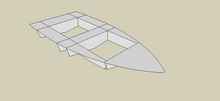 |
You have the internal panels. |
Make this a component.
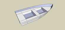 |
And put it back into the bare hull. |
 |
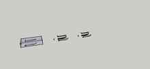
You can now take each of these parts and use them as templates for building the frames. |
You can either have large scale prints made - which can now be had for a reasonable price at plan printing shops. Several do an online service - email the drawing and they'll send a hard copy back.
Or dimension them so that you can mark them out on plywood yourself.
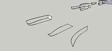
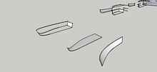
 |
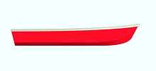
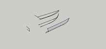
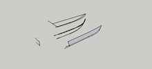
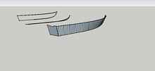
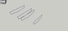
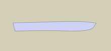
Flatten the hull panels. |
 |
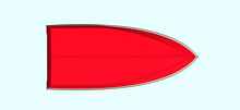
Rotate this panel onto the reg / green axis (ground plane). |
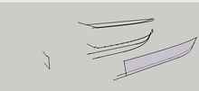
 |
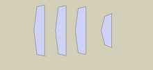
Here are some of the panels ready for dimensioning or exporting as full size pdf's. |
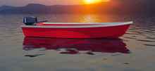
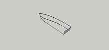
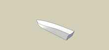
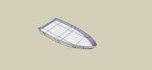
 |
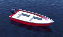
Here's the completed boat. |
After thoughts:
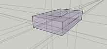
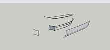
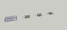
Scaling
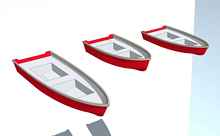
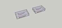
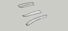
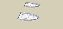
Scaling the model is easy but give consideration to what you want to scale. For example, you might want to make the hull longer but not the seats. If so, scale up the bare hull and then add in new seats.
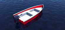
The illustration above shows two alternatives. The boat that is closest has been increased in length to 18' with the height raised for a long shaft outboard.
The one in the middle is the same length as the original (12'), with the height raised for a long shaft outboard.
Frames and frame thickness's
In this exercise, I haven't given the panels any thickness. You could do this by pulling the flat planes out to the required thickness.
I haven't shown a stem, but by now you'll know how to add one for yourself!
|