|
In Part
I of this series of articles on the design and construction
of the sharpie skiff, Nemah, I outlined the preliminary
development of this design.
Working from a notion of what constitutes a "boat,"
lines were developed for a hull that will be well suited
for its intended uses. In Part II of this series, we will
develop a sailing rig for Nemah, and then consider how
to select and apply various structural techniques to create
a boat that is both strong andlightweight
 The Loose-Footed Sprit Rig
There are several sailing
rigs that produce minimal heeling effect. These would include
the gaff rig, the sprit rig, various types of lug and lateen
rigs, and even some low aspect ratio fully battened jib-headed
rigs. In selecting a rig for Nemah, I was influenced by
several considerations, including length and number of spars,
complexity of the rig to set up and handle, relative performance,
appearance, safety, and cost.
Sprit rigs offer several
advantages for boats of the type and size of Nemah:
- The four-sided shape of the
sail itself eliminates the narrow triangular areas that
do little work, as in many three-sided sails
- The sails are generally lashed to the
mast, eliminating the expense of running rigging and sail
track.
- The rig offers the most driving power
in relation to spar length of any known rig
- The short, stiff irast does not need
to be stayed and is easy to step and unstep without assistance
On the minus side, the sprit
must be properly set to be efficient, and the rig cannot
be reefed in the conventional manner, (Sprit rigs are usually
reefed by folding the peak of the sail down and lashing
it off to the mast, and then resetting the sprit to a grommet
set in the leech for the purpo e.)
The point on the hull where
the sheet is made fast while sailing close hauled, needs
to be far enough off the centerline of the hull, so that
the sail can be sheeted down hard and still be able to draw;
hence the wide transom. In addition, the clew of a loose-footed
sail needs to be enough forward of the stem of the boat
that the sheet can be secured at a point
where it places equal tension on both the leech and the
foot of the sail. This usually requires that the mast be
stepped well forward in the boat, which in turn gives two
advantages:
- It moves the center of effort of the
sail well forward, which is needed to counteract the apparent
weather helm that loose-footed sails demonstrate
- it frees up a generous area forward
of the rowing thwart.
Traditionally, the masts
of loose-footed rigs were sharply raked aft. This has the
effect of keeping the pull of the sheet at an optimum angle
through a greater range of points of sail, as well as shifting
the weight of the mast aft.
In drawing Nemah's rig,
I selected a preliminary length of 12 feet overall for both
mast and sprit, and a target sail area of 80 square feet.
Mast rake was determined by eye and the mast drawn in. I
next drew in the foot, with consideration given to head
clearance and so forth. At this point, I pencilled in a
peak angle and found a likely peak height by moving the
sprit around on the drawing until it formed an even-sided
triangle with the top of the luff. I then sketched in the
leech and checked to see if the clew angle and location
would allow the sail to be properly sheeted in, close-hauled.
(The sheet angle in profile should roughly split the clew
angle.)
At this point I checked
the sail area to see if it was coming out near my target
area. (To determine the area of a four-sided sail, first
divide the sail into two triangles, figure the areas of
each, and then add the two together.) If the sail area had
fallen much outside of my target area, I would have had
to adjust the length of one or both of my spars. Small adjustments
can be made by moving the peak around and then relocating
the clew to maintain the sheet angle.
Daggerboard Location
The location of the sail's
center of effort in relation to the hull's center of lateral
resistance determines the "helm" of a boat; that
is, whether you will need to "pull or "push"
on the tiller to maintain your point of sail. Generally,
you want a bit of "weather helm" both for safety
and because a "lee helm" causes the rudder to
work against thecenterboard, reducing your ability to point.
The center of lateral resistance
is the point at which the total of the sideways resistance
of the hull, centerboard, rudder and skeg is in balance.
This point is generally adjusted to fall 10% to 20% of the
hull length aft of the center of effort of the sail, depending
on the rig. In practice, this relationship varies with weight
distribution, the point of sail, the depth of extension
of the centerboard, and so forth. The trim can be "fine-tuned"
by adjusting the rake of the mast, which moves the center
of effort fore and aft.
Because Nemah
is designed to be operated under power, she must meet
U. S. Coast Guard level flotation requirements. Her
wood hull provides a portion of the requirement, but
some additional buoyancy is needed. |
Interior Layout
Once we are satisfied with
the lines of the hull, and the mast and daggerboard locations
have been determined, we can develop an interior arrangement
that will provide for safety, passenger comfort, and structural
integrity. Because Nernah has been designed to be operated
under power, she must meet U.S. Coast Guard level flotation
requirements. Her wood hull provides a portion of the requirement,
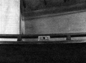
but some additional buoyancy is needed. By fitting an enclosed
seat across the width of the stem, we can supply the needed
swamped buoyancy, give additional stiffness to the transom,
and provide dry seating (see Figure 1).
To provide buoyancy forward,
we can partition off a portion of the hull from just aft
of the stem heel forward. If we reinforce this chamber sufficiently,
we can step the mast to it, eliminating the need for a separate
mast partner.
The location of the rowing
thwart in small boats is always a dilemma. Do you position
it for best fore-and-aft trim when rowing solo, or with
a load? In Nemah's case I have opted to move the thwart
forward of the ideal solo
location for two reasons: (1) it is better to trim a bit
bow heavy when lightly loaded than to trim very stern heavy
with a load on, and (2) under power, the operator will need
to be located fairly far aft, so any passengers should be
seated a bit forward of the center of buoyancy to bring
the hull into trim.
Structural Considerations
Boats are subjected to a
variety of forces, both in use and during storage, We must
account not only for forces generated by the rig under all
points of sail; but for forces applied to the rail structure
under oars, for the thrust of the engine and its associated
twisting forces, for the stresses applied to the daggerboard
well in a grounding, for the localized loading applied to
the hull bottom when someone steps into the boat, and so
forth.
My approach has been to
consider these forces from two standpoints; resisting distortion
that could affect performance, and preventing structural
failure. While these two factors are certainly related,
they are not one in the same. Consider the case of the $39.95
rubber boat under oars the "hull" will flex to
such an extent that the efforts of the oarsman
are almost totally negated, while the structure itself is
in no danger of
failure. Another example of this problem is the loss of
sailing performance noted when the forestay slackens on
a sloop, distorting the shape of the jib. Structural distortion
can also have an emotional effect. Noticeable "give"
when you step into a boat or "flexing" of the
rails under oars can make you uneasy at times.
In open boats such as Nemah,
the two areas where distortion and/or structural failure
are likely to be a problem are both related to the rail
structure. The first is hull twist, particularly under sail,
and the second is rail flex under oars. Traditionally, frames
and bulkheads have been used to maintain hull shape, although
in practice they do little to resist twisting
forces unless used in conjunction with an adequate rail
structure. The rail structure must be stiff enough so that
twisting forces are resisted by the triangular assembly
whose sides are formed by the rails and transom. (This makes
more sense if you realize that hull twist translates to
gunwale movement fore and aft, and that the connection of
fairly stiff rails at the bow will do much to arrest this
movement) In relatively light boats, this can be accomplished
by installing a trussed rail assembly (see Figure 2).
Figure
2
With trussed rail structures
that are made up only of blocks, such as those used in some
canoes, twisting forces caused by the use of oars can still
cause a noticeable flexing of the rails. To counter these
twisting forces, I have adopted the practice of fitting
short ribs between the inwale and the side panel. These
"riblets" usually terminate about four inches
above the chine. Besides adding stiffness in the area of
the oarlocks, these ribs are useful for distributing the
load of the thwart (see Figure 1).
The bending loads on these
rail structures are greatest in the middle and decrease
towards the ends. For this reason, it is acceptable to decrease
the separation between the rubrail and the inwale as it
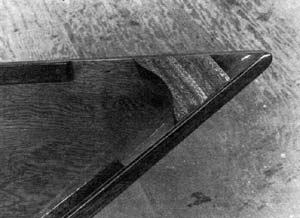
approaches the ends of the hull, and to actually terminate
the inwale just short of the quarter knees and breasthook
(see Figure 3). This simplifies their fitting to a great
extent.
Figure
3
Since Nemah's mast is to
be supported by the forward rotation chamber panel structure,
some consideration has to be given to transferring the sail's
forces to the rest of the hull structure. The simplest way
to do this is to locate the aft edge of the chamber close
enough to the rail structure that the fiberglass tape bonding
the chamber to the hull is integrated into the structure
of the rail itself (see Figure 4).
This relieves the side panel
of the need to absorb a lot of stress in a small area.
Plywood
Because we have given careful
attention to the distribution of stresses throughout the
boat, we can safely use 1/4" marine plywood for the
sides of the hull. Three-ply fir would be satisfactory in
this instance, while 4 or 5-ply mahogany would be a bit
stiffer and somewhat less likely to suffer damage from collision.
By scarphing the bottom
panel with its face grain running athwartships, 5/8"
5-ply fir marine grade plywood will be satisfactory. I generally
sheath the bottom panel inside and out with fiberglass;
outside for abrasion resistance, and inside for resistance
to impact damage.
In Part
III of the series we'll discuss bonding materials and
techniques, and then go through the actual process of fabricating
a plywood composite "shell."

Visit Tracy's website:
https://www.tracyobrien.com/
|