NEMAH: The Birth of a Skiff
Part IV: Trimming
out the Hull and Fitting the Rig
by Tracy O'Brien
https://www.tracyobrien.com/
Part I
- Part II - Part
III
In Part
III of this series of articles on the
design and construction of the sharpie skiff, Nemah, we
went through the process of fabricating her plywood "shell/"
Here in the fourth and final part of this series we will
complete the hull, as well as fabricate and fit her sailing
rig.
A Logical Sequence
 At
this point m the building process, the plywood shell is
structurally complete, but it's still quite flexible,
For this reason, we will leave the temporary spreaders
in place until the rail and thwart assemblies are fitted.
Even with the spreaders in place, the plywood side panels
are flexible enough that they can easily be forced out
of shape. To prevent any possible distortion of the finished
boat, we will need to hold the tops of the side panels
in a fair curve while fitting the forward and transom
bulkheads to the hull. This can be accomplished by fitting
the rubrails to the sides of the hull.
At
this point m the building process, the plywood shell is
structurally complete, but it's still quite flexible,
For this reason, we will leave the temporary spreaders
in place until the rail and thwart assemblies are fitted.
Even with the spreaders in place, the plywood side panels
are flexible enough that they can easily be forced out
of shape. To prevent any possible distortion of the finished
boat, we will need to hold the tops of the side panels
in a fair curve while fitting the forward and transom
bulkheads to the hull. This can be accomplished by fitting
the rubrails to the sides of the hull.
Before bonding the rubrails
in place, we can install the "riblets". They
are glued and fastened to the side panels with short bronze
ring nails driven through from the outside. The rubrails
are then glued up and fastened with bronze ring nails
driven through the side panels from the inside.
At this point, the breast
hook, oarlock blocks and quarter knees are also fitted.
The breast hook and quarter knees are glued and fastened
to the side panels with bronze or stainless steel screws
driven through the knee and into the transom, All screws
should be counter-bored and plugged. The oarlock blocks
are glued and clamped to the inside of the side panels;
no fasteners need be used.
Flotation
With the rubrails in place,
the structures that form the fore and aft flotation chambers
can be installed. We begin this process by fitting the
forward and aft bulkheads at their respective location
lines (which were marked on the side panels during layout).
These bulkheads are wired in place and fillet bonded to
the hull with 3/4" radius fillets on both sides.
After the fore and aft
bulkheads are in place, gluing strips are bonded to the
bulkheads, side panels, and the transom face to provide
bearing for the transom seat and forward deck. Prior to
closing up the forward flotation chamber, the towing eye
and its reinforcing block should be installed, as shown
in Figure 1.
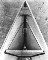
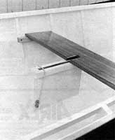
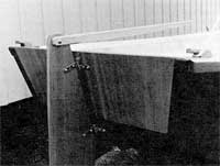
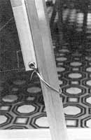
Clockwise from upper left:
Figure 1. Bow eye is installed before the top to theflotation
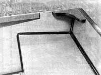
chamber. Figure 2. A 3/4 " radius fillet is applied
to the inside corners formed by theseatfflotation tanks.
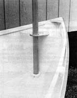
Figure 3. The mast step and mast partner. Note the drain
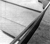
hole in the step.Figure 4. The after ends of the inwales
iaper into the topside panels. (click thumbnails to
enlarge)
The flotation chambers
can be foam filled or left empty, as desired. Coast Guard
regulations only require foam if motors larger than 2
horsepower are specified.
The
transom seat and forward deck (with its doubler in place)
are glued and fastened in place with bronze ring nails,
and then a 3/4" radius fillet is applied around their
entire perimeter (Figure 2), The aft upper edge of the
forward deck is bonded to the side panels with three layers
of fiberglass tape, as was mentioned in PartII
of this series. This helps distribute
the stresses developed by the sail rig to the rail
assembly.
The Inwales
After the forward deck
is bonded in place and its reinforcing tape is sanded
smooth, the inwales can be fitted. They are cut to length
and their aft ends are taper cut to join the side panels
prior to installation (Figure 4). They are glued and fastened
in place with 1-1/4" bronze or stainless steel screws
driven into the side panels aft, and into the inside faces
of the nblets in the mid section of the hull. The forward
ends of the inwales are fastened to the side panels from
station #152-1/2 forward, as shown in Figure 3.
The fore and aft rail
spacer blocks can now be glued and clamped in place (Figures
3).
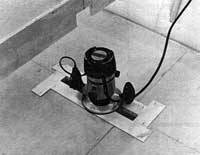
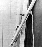
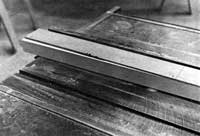
Clockwise from upper left: Figure 5.
A simple template can be used to rout the hole for the
daggerboard case. Figure 6. The center thwart is notched
to clear the daggerboard. Figure 7. A taper jig can be
used to taper cut the spars on a table saw. Figure 8.
The butt of the sprit is drilled to accept the snotter.
(click thumbnails to enlarge)
The Daggerboard
Well
The daggerboard well consists
of two side panels, two spreader blocks, and two well
beams. It is assembled and trimmed to fit prior to installation.
The hole into which the well is fitted can be cut with
a saber saw or with a router fitted with a guide bushing,
as shown in Figure 5. Note how a temporary pattern is
assembled by stapling plywood strips to the hull bottom.
The advantage of this technique is that the finished opening
will require no further cleanup work.
The case is glued and
fastened to the bottom panel with two temporary screws
driven up into the ends of the well spreader blocks. Shims
are placed between the bottom edges of the well side panels
to prevent distortion, and then the well assembly is fillet
bonded and taped to the bottom panel.
Two thwart cleats are
fabricated from white oak and fastened to the riblets
at a point level with the top of the daggerboard well.
The thwart itself is fabricated from 3/4" mahogany
and is notched to provide clearance for the daggerboard,
as shown in Figure 6. The thwart is fastened to the daggerboard
well beams and the thwart cleats with bronze or stainless
steel screws.
Mast Attachments
The mast is fitted by
simply dropping it through the mast partner and fitting
the mast heel into the mast step, as shown in Figure 3.
The mast step is fabricated from 5/4" white oak and
is glued to both the bottom panel and the forward bulkhead.
It can be held in place with temporary screws driven up
through the bottom panel. (Note that the mast step is
fitted with a limber hole.) The mast partner is fabricated
from 1/2" or thicker marine or aircraft plywood and
is fastened to the forward deck with five #10 x 1-1/2"
stainless steel screws.
Finishing the
Hull
After the rail assembly
and flotation chambers are fitted, the temporary spreaders
can be removed and any remaining holes in the hull filled
with thickened epoxy. The tops of the rails should be
belt sanded and faired into the transom top, and so forth.
All trim work should be
given a coat of penetrating sealer. Some or all of the
trim can be left natural, as desired. On the prototype,
I opted to paint the majority of the hull, leaving only
the transom, rubrails, quarter knees, thwart assembly
and mast partner bright. All brightwork was finished with
gloss spar varnish. Single component urethane marine enamels
were used on all the painted surfaces. A small amount
of Grumbacher cobalt drier was added to both the varnish
and the enamels prior to application to speed drying,
as these finishes are often quite slow in drying when
applied over epoxy coated surfaces.
Fabricating the
Rig
Nemah's sailing rig consists
of five major components: a 12-foot mast, a 12-foot sprit,
a daggerboard, a rudder and tiller assembly, and an 80
square foot spritsail.
The mast is fabricated
from a 2" square by 12' long piece of clear fir or
spruce. The blank can be laminated from a number of pieces,
if required. The top 2 feet of the blank is tapered on
two adjacent faces to form a 1-1/2" square, when
viewed from the end (Figure 7). The blank is then chamfered
on all four corners to form an octagon. The heel is tapered
slightly all around to fit into the mast step, and a shallow
groove is cut around the mast head to provide a secure
place for lashing on the sail throat.
The sprit is fabricated
from a 1-1/2" square by 12' long piece of clear fir
or spruce. Each end of the blank is tapered on two adjacent
faces, with the taper cuts running out at 3 feet, leaving
a 1-1/4" square at each end. The sprit is then chamfered
on all four corners to produce an octagon, as with the
mast. The top 1" of the sprit is reduced to 3/4"
in diameter, leaving a shoulder to catch onto a rope loop
fitted to the peak of the sail. The butt end of the sprit
is drilled to accept the snotter, as shown in Figure 8.
Both mast and sprit are
given a coat of clear sealer and several coats of spar
varnish.
Above left: Figure 9.
Oak cleats, fastened to the quarter knees, are used to
turn the sheet back to the cockpit. Right: Figure 10.
The sail is lashed through a small pad eye to provide
tension on the luff. (click thumbnails to enlarge)
The daggerboard is cut
from 3/4" x 12" hard mahogany, and is fitted
with a cleat at its upper end. The lower leading edge
is given a 6" radius and the entire underwater profile
is faired off to a streamline section. The daggerboard
is held in place by a short length of shock cord, as shown
in Figure 6. The rudder can be cut from a length of 3/4"
x 10" hard mahogany, and is radiused and streamlined
as described above. It is fitted with bronze or stainless
steel pintles, and will require a keeper to prevent its
floating out of the gudgeons. The tiller is fabricated
from two lengths of 7/16" thick white oak, with a
13/16" mahogany core, the whole unit being epoxy
bonded together. The forward end of the tiller is tapered
to a comfortable thickness, and all edges are given a
1/4" radius. A 1/4" bronze or stainless steel
carriage bolt and self locking nut are used to assemble
the tiller to the rudder (Figure 9).
Daggerboard, rudder, and
tiller can all be finished bright or painted, at the builders
option.
A pair of oak cleats should
be fabricated and fastened to the quarter knees, also
shown in Figure 9. These provide a simple method of routing
the sheet from the quarters back into the cockpit.
Besides the bow eye, pintles
and gudgeons, and rowlock sockets, the only other hardware
requirements are a jam cleat to secure the snotter to
the spirit (Figure 8), and two small pad eyes, which attach
to the mast to prevent the sail lashing from riding up
the mast (Figure 10) and the snotter from sliding down
the mast,
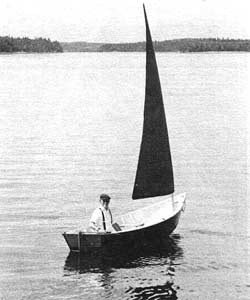
Performance
I have sailed Nemah in
a variety of conditions, from the light air of Olympia's
Boston Harbor, (where the rowing and sailing photos were
taken), to the gusty winds and choppy conditions of the
Ilwaco channel at the mouth of the Columbia river. On
Seattle's Lake Union she easily overtook a generously
canvassed traditional sloop while sailing close hauled
in a 6 to 8 knot breeze!
To windward, the loose
foot sets well, and actually is not much different than
a boomed sail, except that you can control the shape to
a greater degree with the loose foot. Downwind, the sail
bellies out, owning to the lack of a boom, but as the
sprit gives it shape at the peak, the sail performs quite
well, and doesn't tend to roll as much as most cat rigs
do on a run. The rig's low center of effort is quite noticeable;
even in a gust. I have been able to keep her on her feet
without having to sit up on the rail.
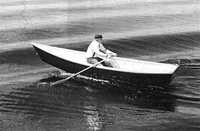
Under oars, Nemah is a
delight. Rowing solo, the hull trims a bit down at the
bow, which keeps her quiet and on track. With one or two
people in the stem, she is well balanced, moving easily
and going where she's pointed. I'm quite pleased at her
speed under oars; she carries well between strokes and
is not unduly hampered by the wind. I had an occasion
to row her dead to windward with board down and sail luffing
while in the Ilwaco channel, covering just under a mile
in 20 minutes.
At about 135 pounds without
her rig, she would take two adults to car top, but can
easily be handled by one person from a trailer or the
bed of a pickup. I've got the prototype on a trailer fabricated
from an imported trailer kit. I fitted it out with bunks
running across the width of the frame and bolted on a
10-foot tongue made of a nice piece of dry fir. The whole
towing package weighs under 300 pounds, and can be disconnected
from my mini pickup and rolled down to the water's edge
if no ramp is available.
Working out the design
of Nemah, and building and sailing the prototype has proven
to be both rewarding and enjoyable for me. I'm certain
that should you choose to build Nemah for yourself or
your family, you'll also find the building to be simple,
yet satisfying, and the sailing to be fun.
Plans and instructions
for Nemah
are $55 from Ken Hankinson and associates or from:
Tracy O'Brien Marine
Design
156 Bunker Creek Rd.
Chehalis, WA 98532
(360) 748.4089
fax (360) 740.0504
(tracy@tracyobrien.com)