The 9.5 Laura Bay - Part 5
|
|
|
design by Warren D. Messer - Seattle, Washington - USA |
Part
1 - Part
2 - Part
3
- Part 4
- Part 5 - Part
6
This part of building the Laura Bay
will deal with the sailing rig and it‘s accessory
systems. I was going to go into the construction of
the NACA 0000 foil sections of the daggerboard and
rudder, but have decided to do that in a separate
story from start to finish. The daggerboard and rudder
for the Laura Bay were completed before I had my own
digital camera and much of the details that I wanted
to convey could not be shown. I will show some photos
of the results, so you can see that a foil shape can
be accurate and easy to construct.
For my mast parts, I made a visit to www.onlinemetals.com‘s
shop in Seattle. Very helpful people and I was in
and out in under 30 minutes with my mast, boom, and
sprit tubes. I also watched them pack up some orders
for shipment by UPS and would say that nothing should
ever get damaged in transit.
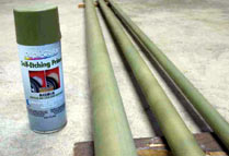
Once I got the tubes home, I gave them a light sanding
with 600grit and a good cleaning with a soft cloth.
It took me a while to find a retail outlet that had
"etching" paint for aluminum, but I found
it at a local auto supply store. I don't know if the
"Shucks" chain is national or not, but I
would imagine that any large auto supply store near
you would carry the same product. I gave the tubes
two coats and let them cure overnight. I later painted
them with some gray acrylic latex paint I had sitting
around, but wished I had used some of the left over
System Three WR-LPU, two part polyurethane paint I
used to paint the hull on the 8ft Nuthatch. That stuff
is tough and easy to work with and clean up. I also
inserted foam into both ends of all the tubes for
floatation and to limit the amount of water that could
enter if submerged in a tip over. I had some high
density closed cell foam left over from my first whitewater
kayak that died of UV poisoning. Just place the tube
on the foam and twist. It drills the correct sized
hole as it goes through the foam. Just push it in
a bit for the fittings on the ends of the boom and
sprit to fit.
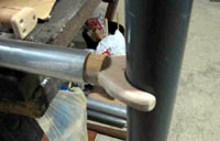
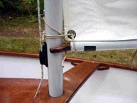
Not much needs to be done with the mast, other than
drilling some holes for the various eye fittings and
snotter hook. The sprit needs to have pins in the
ends of the tube for the sail and snotter line to
attach to. For this I found that some 7/8” dowel
(old broom handle) works with just a bit of light
sanding for a snug fit inside the sprit tube. The
photos and plans show how to do this. Just drill a
5/16-3/8” hole off set to one side in the dowel.
You will insert a smaller dowel into this and have
it protruding out at least 1” from the end.
I used some 5/16” fiberglass doweling I had
laying around. A hardwood dowel (birch or oak) will
work fine. Assemble all the pieces into each other
and drill a hole through the tubing and dowels and
use a round headed #6 x ¾” stainless
screw to hold it all in place. Do this to both ends
of the sprit.
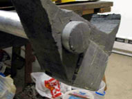
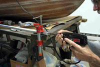
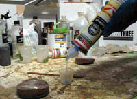
The boom needs to have fittings made for both ends.
One to act as a gooseneck (yoke) and one to act as
an outhaul. I made the yoke out of three layers of
6mm scrap laminated together. I also cut off two small
outside edges of 1 ¼” doweling I had
laying around to make the part that goes into the boom
tube large enough in diameter to fit tightly. Once
it was all cured, I laid out the mast tube radius
and shaped the horns. It was then shaped, smoothed,
stained, epoxy coated, and inserted into the tube
and held in place by a round headed #6 x ¾”
stainless screw.
For the outhaul, I copied the shape that the Optimists
use, but out of wood instead of molded plastic. I
used a 2” length of 1-¼” doweling
for the outhaul plug and attached the end fitting
(scrap of 3/8” oak molding) with GelMagic
and a #8 x 1 ½” stainless screw. The
plans show the location and sizes of the holes to
drill in the outhaul end piece. Everything is shaped,
finished and coated with epoxy; inserted and held
in place with a #6 x ¾” stainless screw.
All exposed wood was later coated with varnish.
The mounting positions of all the various running/standing
rigging fittings are shown in the plans.
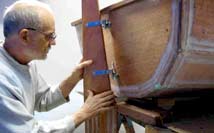
On this design the relationship of the CLR and CE
put the mast back farther than I wanted the bow seat
to extend. I was toying with the idea of a removable
mast partner and having it attached higher on the
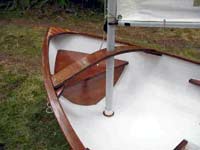
hull than just being at the top of the seat. The first
idea was for a flat partner that was attached to “wings”
epoxied to the sides and under the inside rails. I
wondered what an arched partner would look like; so
I took a scrap of 6mm ply and clamped it to the rails.
There was no going back to straight.
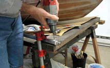
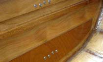
Before I could mount the mast partner, I had to
locate the positions for the partner “wings”
that are attached to the hull. I had the shapes cut
out of ¾” material I had left over from
the trim. After finishing and staining the two wings
I clamped them to where the design said they were
to go and to see if it looked right. The facing edges
were shaped to fit the hull sides and three #6 x 1”
stainless screws were drilled for and placed to hold
each wing temporally for a final check. The wings
were removed and the two gluing surfaces on each wing
were coated with GelMagic and reattached with the
stainless screws and lightly clamped. The wing to
hull side angles were rechecked again, and left to
cure overnight.
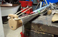
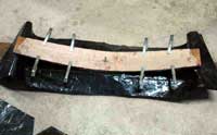
I looked around the shop and found three pieces
of scrap that would work and trimmed them to their
finial shapes. I took an old 2x6, drilled a 5/16”
hole in the middle of it and the three partner pieces
and dry fitted them with a 4” carriage bolt
(threads up). I covered the 2x6 with plastic, slathered
up the partner pieces on their mating faces and assembled
them in the mold. I put scraps of 3 ½”
hardwood t&g flooring under the ends(under the
plastic), and moved them in until I had the end to
end cord length I needed to span the gap between the
rails where the “partner wings” would
be attached to the hull sides. I then let the partner
assembly cure over night. The next day I trimmed the
ends and rounded the edges.
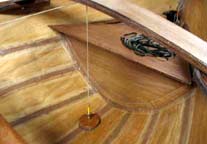
To make the opening for the mast, I had to make
sure that the original 5/16” hole was close
to the centerline of the boat. Back out come the strings
and pencil bobs, and making sure the boat is level
side to side and close to what I thought (wished)
the fore and aft trim should be. Once I had the boat
level and trim, I could then mark the center of the
opening for the mast in the partner. I also had to
make sure the ends of the partner were equal fore
and aft, marked, clamped and drilled into the partner
wings. The mast opening was marked, cut (oblong the
opening fore and aft a bit, to counter the slight
angle from horizontal of the partner, and let the
mast fit and rotate), and the edges rounded over.
I later added a "keyhole" cutout to the
port side of the opening to allow an eye for a vang
attachment and a anti-mast losing pin to pass through.
Both are offset from each other, so you have to rotate
the mast a little between each part going through
the mast hole. It can't come out on it's own now or
lift off the mast step when running.
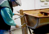
Once the mast hole was cut, I had to locate the
mast step position in the hull. I dropped a longer
stringed pencil bob through the hole and marked the
location on the hull. My mast step was going to use
a 2” PVC “plug”(the kind that fits
inside the pipe) to hold the bottom of the mast. The
plug has a 2” ID and was a perfect (cheap) fit.
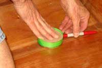
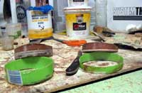
To mount the plug, I needed something to fill in and
level out the “V” in the keel, and make
it perpendicular to the mast. I used my old gap filling
standby EZ-Fillet, a 1” section from a 3”
diameter plastic bottle, and a plywood circle cut
to fit inside the plastic ring. Slide the plywood
into the plastic ring, set them on the bottom of the
boat, and hold a marking pen next to the hull as you
mark a line around the plastic ring; then cut along
the line with scissors. Press the plywood circle to
the upper (level) edge and check the fit, and trim
the lower edge as needed so the surface remains perpendicular
to the mast. This is important, as its a close fit
between the mast and the inside of the PVC plug. Any
mismatch and the mast binds inside the plug. It can
be shimmed later with stainless washers if it's off.
I had a 4 foot length of thin wall 2” OD electrical
conduit that I used as my mast tester. I placed the
plastic ring in position, set the PVC plug on top,
and inserted the mast into the plug. I then checked
for level and true again. Once I was happy with the
fit, I mixed up some EZ-Fillet; then filled and shaped
it to the contours of the plastic ring and let cure
overnight. The rings were then attached to the hull
with a layer of GelMagic, positioned, and left to
cure overnight. The PVC plug is then drilled through
it's center and screwed to the center of the mast
step attachment point after sanding and coating the
plywood ring with a layer of epoxy.
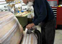
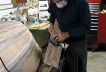
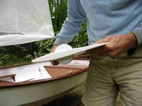
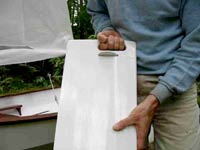
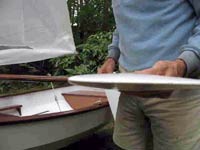
The daggerboard and rudder are designed to be NACA
0000 foils from the Naca4gen program. I take the information
the program spits out and enter it in my drawing program.
The daggerboard is a NACA 0010 and the rudder is a
NACA 0012. The 0010 gives the ratio of the thickness
cord to the distance back from the leading edge of
the daggerboard. I used a width of 10" (not a
part of the 0010)and the thickness cord came to be
around 1" at 30% from the leading edge. The rudder
I set to 8" wide and the cord width came out
at 1" also, but the upper part where the pintles
go is only ¾" thick. I'm able with the
software I use to draw this out with an end view;
and then figure out how to stack 1/8" (3mm) plywood
of various widths and lengths, to get the outline
of the foil shape. Then it's cut out the pieces, coat
with epoxy, stack, and let cure. I then mix up the
EZ-Fillet and fair in between the stairstepped edges
of the plywood stack. Then its sanded down and final
faired with epoxy thinned Quickfair; then finish sanded
and coated with Silver Tip epoxy, and sanded fair
again. I then roll on three to four coats of either
System Three's two part WR-LPU, or their Marine Enamel
to finish it off. The construction of the rudder and
daggerboard is more involved than this and will be
expaned in greater detail in a later story.
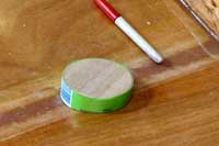
Now its time to mount the rudder and it's hardware.
You need to know where the centerline of the boat
is on the stern panel, and to establish those reference
points. I place pieces of the "green or blue"
masking tape where I think the centerline is, and
mark the true position on the bits of tape with a
pencil. On this boat you need to shorten the pins
on the pintles so you can mount the upper gudgeon
high enough on the stern panel for strength and still
let the top of the upper pintle clear the outer aft
stern rail. So I place the shortened( pin) upper pintle
in a gudgeon and determine it's mounting position,
and still have the head of the pintle clear the rail
when lifted out. Mark one of the holes and drill it.
Use one of the machine screws and nuts to hold the
gudgeon in place while you aline, mark, and drill
the second hole. Use another machine screw and nut
to keep everything lined up as you drill the last
two holes. Measure down from the upper gudgeon, the
distance listed in the plans and mark with a bit of
tape. Line up the lower gudgeon on the stern's centerline
and mark the first hole.
One of the things you can do to make this go easier,
is to take a piece of 3/8" doweling (this boat
uses the medium pintle and gudgeon kit from Duckworks
BBS) at least 1 foot long, and use it to act like
a long pin and hold the gudgeons in line on the centerline
of the stern panel. That way the upper and lower gudgeon
pin holes are forced to be in a straight line if the
dowel is straight too.
Repeat the drilling and bolting sequence you used
earlier to mount the lower gudgeon. Don't tighten
the machine screws and nuts down yet, just snug.
Set the rudder height so the top of the foil section
is just below the bottom of the hull at the stern.
Insert the pintles into the gudgeons (short pin on
top) and bring the rudder into the tangs of the pintles.
I use a couple of clamps to hold the rudder in place
while I fiddle with the fit. I also use the 3/8"
dowel again to determine how far the rudder is inserted
into the pintle tangs. Just another way to keep everything
lined up. Once the rudder is at the right height,
and tight against the dowel in the tangs, I clamp
it down tight and check the swing from side to side.
If everything is ok, I drill the forward holes in
the tangs first and insert a #10 round headed machine
screw into each, and tighten with a Nyloc nut. Check
the side to side swing again, and if all is still
good, drill and mount the second set of machine screws
and nuts. If this was a perfect world, it should swing
with no squeaks or grinds, but it isn't, so you have
to just say (if it's not too bound up) that it can
wear in. If you used the dowel trick, everything should
be ok or at least close enough for Red Green. ;)
Now take off all the hardware from the hull and
rudder and get them ready for their final finishing.
Take a countersink bit and cut a slight bevel into
the outside holes of the stern panel for the lower
gudgeon's machine screw holes. These will be filled
with sealant to keep out any water that tries to get
in. Its also a good idea to give the inside of the
holes a light soaking with epoxy.
Once the hull and rudder are painted and cured,
the pintles and gudgeons can be installed. Re-insert
the machine screws (I put the heads on the inside)
and put a good bead of calking sealant around them
filling up the countersink bevels (plus some extra)
you made on the outside of the hull. Replace the gudgeons
and tighten all the machine screws and nuts. Scrape
off the excess sealant that squeezes out. Mount the
rudder again and pray that it still swings free. A
little polishing with some emory cloth on the pins,
and some honing with a small rat tail file can free
up a sticky rudder.
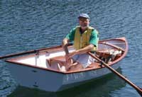
This will conclude the series of stories on the
construction of the 9.5 Laura Bay, but I will have
a follow up article and photos of rigging the sail
and the sea trials. Look for the plans to be on sale
soon as I double check all my drawings for the final
changes that I have made.
Thank you again for reading my stories and the comments
you post.
Warren Messer
Red Barn Boats

|