| Part1
- Part2 - Part3
- Part4
Last time
got though most of the new framing on the light schooner’s
new motor well rebuild. Now we’ll finish her
up.
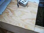
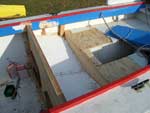
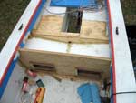
Here’s where we left off: (click images
for larger views)
Slop Well
We talked a little about slop wells in the first
installment, but let’s review. A Michalak-type
slop well adds great stiffness with little added weight,
gains back some lost sealed buoyancy, adds storage
compartments, and helps water and spilled fuel drain
more gracefully from the motor well. You can’t
beat that. Here’s what it looks like on an AF4B.
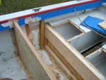
The slop well is simply a panel connecting the motor
clamp bulkhead to the motor well bulkhead. The resulting
box is very strong and stiff. Instead of using a flat
panel, though, I used a separate panel for each side,
so the slop well could drain to a single center point,
emptying into the motor well through a hole in the
motor board. This requires more nailer strips, but
first we have to make the lines.
First we find the lowest point of the slop well.
This will be on the centerline below the motor. It
needs to be low enough to stay out of the way of the
motor’s steering cables, if applicable. For
me that was about 4.75” below the top of the
motor board, 4” below the top of the bulkhead.
I also assumed motor steering for the outboard sides,
in case I ever wanted it. Knowing the position of
the motor sheaves, I can determine where the springs
and sheaves for the cable will anchor. The vertical
frames I added provide a spring point for anchoring
steering hardware, and we know from OMC’s literature
that the anchor points should be vertically within
1.5” of the motor’s sheaves. Closer is
better, but I marked the maximum.
These points allow me to determine the upper surface
of the aft edge of the slop well deck, so it won’t
interfere with the cables. Don’t forget this
line is the top surface. You need to make another
line below this line by the thickness of the plywood.
I was going to use ¼”, but I decided
3/8” would be prudent. This is the kind of place
where a swimmer climbing back into the boat can trip
and put a foot through it. 3/8” is plenty strong
enough and doesn’t weigh much more for such
a small deck.
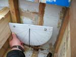
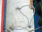
In this photo I enhanced the slop well lines. The
small Xs on the vertical 2x2 frame are where the motor
cable sheave and spring get anchored.
Now we need to decide on the fore-and-aft slope of
the slop well. I decided that 5 degrees was enough,
but that it had to be 5 degrees when the trailer was
parked. Probably more like 7-8 degrees when the boat
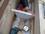
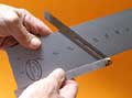
is level. I used my clinometer to measure this angle,
though a level and protractor would also work. Note
how I held a straight scrap of wood against the clinometer
to transfer the line to the opposite bulkhead.
Be sure you transfer these points with the clinometer
lined up parallel to the centerline. Otherwise you
might end up trying to twist plywood. It doesn’t
like that.
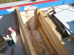
With points transferred at each side and amidships,
then can be connected to form the lines for the forward
edge of the slop well decks. I transferred the line
for the nailers instead, skipping the upper line entirely.
Then it’s a simple matter of connecting the
lines all the way around. Here’s the enhanced
photo again.
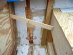
Now we need the correct bevels so we can rip nailer
strips. This seems like a real brain bender, but really
it’s not. I found a piece of scrap wood, broke
it to length and wedged it between the fore and aft
bulkheads so it’s upper surface lined up with
the nailer lines. Then I could measure the bevel from
the aft bulkhead and side.
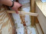
To get the bevel correct, the leg of the bevel gauge
that is on the bulkhead must be perpendicular to the
nailer line. It’s easier if use a square (or
any handy rectangular box) to draw such a line. You
won’t have enough hands to hold yet another
tool. Be sure to record and label bevels immediately.
On the deck is easiest if you’ll be painting
it anyway.
Only two bevels? Not quite. Those two take care of
the sides, front and back. You get the rear bevel
by subtracting the 15 degree tilt of the motor clamp
bulkhead from the front bevel. But we still need a
nailer to serve as a “spine” where the
panels join in the middle. If I had a tablesaw at
home, I might have cut a concave double bevel to do
this. But with only a circular saw I thought it better
to cut two separate strips and fasten them together.
This bevel can be measured directly off the motor
bulkhead – between the vertical centerline and
the nailer line.
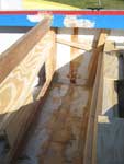
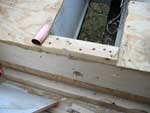
Fastening the nailers is nothing complicated. But
pre-drill or these little sticks will split. This
is just as well, since we should really dry fit any
assembly with so many bevels. It’s a lot of
opportunity for error, so I’d like to know it
all fits before getting out the glue.
This is also a good time to dry fit the hatch frames
for the access between the aft cockpit and the newly
created storage under the slop well. These frames
should be on the forward side of the motor well bulkhead.
That way you have a place to install screweyes for
the shock cord that retains the hatch cover. I think
it is easiest to draw the hatch opening on the aft
side, cut it, then frame it.
The decks are easiest to make by spiling, just like
we did for the bulkheads. (They are already white
because I was using scrap that was already painted.)
Good, it all fits. (Except that bit under the wide
decks where you really have to piece it together later.)
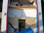
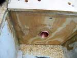
But before we glue it into place, we should fit the
scupper that will drain this slop well into the main
motor well. I used a scrap of 1” copper plumbing
pipe I had laying around. I’m sure ¾”
would be fine. I cut the hole so it would be a little
below the level of the slop well decks. This is why
we install this part before the decks. We don’t
want any water pooling there, right on a glue joint.
I bored a pilot hole, then finished with a spade bit.
After shining up the metal with sandpaper, I glued
it in with PL400. I would have preferred epoxy putty,
but epoxying temperatures were still months away.
Here you can save some effort if it’s warm
out. Glue in the nailer strips and hatch frames. When
these cure, trace the hatch openings onto the hatch
cover stock while you can still get to both sides.
Then prime and paint all this new construction, including
the underside of the decks. This means much less mess
trying to paint all surfaces of the inside of a closed
compartment. Unfortunately, like I said, it was too
cold to paint. So I had to deal with a well-painted
arm in the spring.
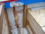
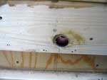
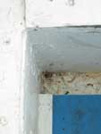
Drain holes
It may seem strange to bore drain holes in an open
motor well. But the water tends to collect just forward
of the slot when the boat is on the trailer. These
holes allow it to drain. Be sure the end grain is
thoroughly sealed with epoxy. Better yet, epoxy in
a piece of 1/4” copper tubing like I did. It’s
hard to see in the crud that collects in the corner,
but it’s there.
These holes are small enough that they don’t
let in much water underway, but they are plenty to
drain the motor well at rest. This is much better
than having to reach around a greasy motor to sponge
up a couple ounces of water every time I trailer the
boat or it rains. And obviously it’s much better
than letting water collect there.
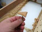
Draining the Corners
Since we added the full-height motor bulkhead frames,
there is a little pocket behind each where water will
tend to collect. This is bad. One way to drain it
would be to cut a limber hole through the frame itself.
This works, of course, but it’s a real pain
to paint the inside, and you have to remember to cut
such a hole before installing the frame. I wasn’t
100% confident of where it would need to be, so I
went the other way.
By elevating the deck in that pocket, water is forced
to drain. I did this with some small triangles of
scrap plywood. I used one screw and “gooped”
them into the corners with PL400 and a single deck
screw.
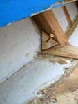
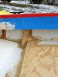
They look better once they’re painted. Still
not beautiful, but functional and unobtrusive under
the side decks.
Aft Hatches
Now we have two unventilated spaces to the sides
of the motor well. This is bad in a wooden boat because
it encourages rot. We need to add new hatches to replace
the ones we removed. This time I did it the smart
way and set up the motor and steering and everything
and went boating with it. Then I could draw on the
decks where I wanted to put gas tank chocks and hatch
openings. I think it’s important to do it this
way, because your first idea might not allow for the
movement of the motor or steering cables.
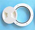
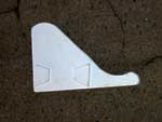
Normally I’ve been pretty satisfied with the
Michalak-style plywood hatches, but this situation
is a good case for using a ¼-turn
access plate. I don’t need to really
store stuff inside these air boxes now that I have
the much more convenient hatches under the slop well.
More importantly, I probably shouldn’t store
stuff there, since the motor and fuel provides plenty
of weight there already. I’ll want that air
to support the machinery high and dry if I ever capsize.
But I still need an access plate so trapped moisture
doesn’t rot the hull.
On top of that it is pretty easy with such a motor
well to wind up in a situation where the hatch has
to be under a fuel tank. I’d avoid this because
it is an extra step when trailering, but a flush hatch
might be handy if you ever make a long trip under
power and need to carry extra fuel.
Finally, a flush hatch is good here because this
is where swimmers climb back aboard and there’s
already too much junk back there with the machinery.
It is one less thing to trip over in an area where
you really don’t want to trip.
And as it turns out, Duckworks has some decent access
plates that are cheap enough for even
someone like me to consider them. (I nearly fell out
of my chair when I checked the prices of comparable
products through one of the major marine suppliers.)
They are easy to install too. Trace the hatch and
cut a hole that fits it but doesn’t pinch it.
Screw it in lightly with some silicone RTV sealant.
After the silicone cures, tighten the screws a little
to put the “gasket” under tension. (Thanks
for David “Shorty” Routh of www.shortypen.com
for this technique.) I put them right next to the
motor because the fuel tanks can’t go there
or they would interfere with the motor’s steering.
Again, be sure that the hatches drop into the hole
without forcing them. If you have to force it into
place, the hatch will deform and it will be difficult
or impossible to attach the cover. Speaking of the
covers…
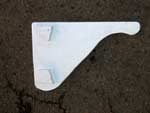
On the product page, Duckworks points out that these
access plates can be difficult to open when you can’t
get your wrist at just the right angle. To remedy
this problem, Chuck screwed on scraps of wood to provide
a better handle. I wanted to keep them relatively
flush, so I did it the other way around. I made a
“key” from scrap plywood to increase leverage.
The keying is repeated on the other side, but rotated
90 degrees, so I can always find a workable angle.
Of course flush hatches have their downside as well.
When the boat is parked and they are open, rainwater
is more likely to get in the compartments if it blows
under the tarp. In practice it’s been less than
a spongeful, so far.
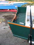
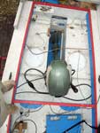
Fuel Tank Chocks
Here’s the final touch. The fuel tanks are
held down by three eyebolts and shock cord. The cord
belays to the two on one side, both parts run through
the tank’s handle, and an S-hook attaches the
cord to the eye on the other side. If the eyes are
close enough to the tank, they also serve as chocks
to keep it from sliding around. Note, however, that
these are 2.5-gallon tanks. You might need more than
shock cord for the heavier standard 6-gallon variety.
Placing these tanks was trickier than it looks. It
looks like there are many options for locating the
tanks, but you can’t use most of them if you
ever want to steer with the motor. I found that steering
with the rudder was almost always just as good, but
I still wanted the motor steering as a backup. So
where you see them is really the only place they fit!
I think this reinforces the idea that outboard motors
are much better hung on the transom.
In any case this is an improvement over the earlier
motor well. The motor can tilt up all the way and
be steered with cables (maybe not so useful after
all), all the “slop” drains freely from
the boat both in the water and at rest, we gain back
lost freeboard astern, and the hatches are actually
useful.
On the design
In spite of my complaining, one shouldn’t imagine
that I fault Bolger for the original design “flaws”.
This is just one of the things that can happen when
one tries to adapt a racing design for knockabout
sailing, auxiliary, and power launch use. Had I fully
thought out the different application I might have
made these changes before actually building. Or I
would have skipped the inboard motor well entirely.
Bolger remarks in Boats
With an Open Mind that he doesn’t
like inboard motor wells and only designs them when
his arm is twisted. I think he’s probably right.
Think twice before you decide that one of these monsters
is a good idea. And if you find yourself twisting
a designer’s arm, listen to him instead!
Rob Rohde-Szudy
Madison, Wisconsin, USA
robrohdeszudy@yahoo.com

Click
Here for Other Articles by Rob Rohde-Szudy
|


 Bevel Gauge