When you make the jump from a sailboat with an auxiliary 5.5 hp motor to a motorboat with an 18, you start using a lot more fuel. This gets you thinking little harder about measuring the fuel you are using.
The obvious reason for measuring fuel use is knowing whether or not you will make it back home on the fuel you have. But there are other reasons. Comparing the efficiencies of various engines is one. Another is finding the most efficient rpm on the engine you have. Yet another is measuring the effects of modifications. And finally, monitoring fuel consumption can sometimes provide early warning of mechanical problems.
Measuring Fuel Consumption
So let’s look at how to measure fuel use.
How the pros do it
Of course there are marine and industrial fluid flow measuring systems. If you have a diesel you can only do it this way. A diesel uses the fuel to cool the injectors, so it always pumping excess (hot) fuel back to the tank. You have to measure both sides and compare them, which is more complicated than I would want to mess with. I think this might also be the case with fuel injected four-stroke gasoline engines. Note that your car probably has three fuel lines. I think those are the feed, fuel return and vapor return. Suffice it to say that things are much simpler (and cheaper) with one-hose two-stroke outboards.
The Michalak Method
The only effort I know of to measure fuel consumption in old outboards was made by small craft designer Jim Michalak. The results can be found in his book, Boat Building for Beginners (and Beyond!). Here’s how Jim did it.
 click images to enlarge click images to enlarge
Basically he used a soda bottle of constant diameter as a graduated cylinder in place of the fuel tank. He had to switch the fuel line to this little tank, pump the primer, and run the engine until the fuel got down to the starting line. Then he would time the run until the fuel burned down to the finish line. Knowing the time, speed and volume, he could calculate efficiency. If you do it this way, don’t forget the little vent hole in the cap!
The trouble he found is that his bottle only had a narrow range of linear response. Beyond a certain point fuel would cease to be drawn from the bottle, and instead would seemingly be drawn from the primer bulb.
Gravity Feed
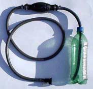
The main problem with Jim’s system is the unknown influence of the primer bulb. Let’s get that out of the picture. We do this by feeding the fuel by gravity, and using the primer bulb only to pump fuel into the measuring bottle. This means we need some kind of siphon-breaker and a measuring cylinder. It would be nice to have valves to switch from tank to measurement system, but I couldn’t see spending $30 on plumbing parts for that convenience. I just unplug one fitting and replace it with the other as fast as I can, so the carb doesn’t lose too much of its prime.
Here’s how it works if you use a bottle:
You use a primer bulb (or other pump) to pump fuel into the jar from your spare fuel tank. Then start timing as the level passes a mark. You can run from the measuring bottle for as long as you feel like pumping fuel into it.
Bottles
Making space for three fittings on the lid limits our choice of bottles. Two 1/8” pipe fittings and a vent will not fit on the lid of the average soda bottle. Maybe with one of those wide mouthed 20-ounce or one-liter bottles. But it seems that the lids are made of a plastic that doesn’t glue readily. For a small motor a glass spice jar with a metal lid might work, since epoxy will stick to roughed-up steel. Just remember you’re looking for tall and narrow, but not tapered. Maybe a fancy olive oil bottle. I think some fancy liquor comes in tall, narrow bottles too. But look for something sturdy. Broken glass and gasoline all over the cockpit cannot possibly be a good thing.
But I made mine a little differently. It might actually be less work than fighting with these bottles.
Narrower
We can make this thing thinner for better resolution if we can use both ends of the tube, so only two fittings on a given end are needed. Here’s how it is laid out.
This lets us get away from glass. I used a cheap polypropylene laboratory graduated cylinder. The cheapest I’ve seen is at www.usplastic.com, mostly because their shipping costs were within reason and there was no minimum order. $4.20 for the 250 mL graduate, and about the same in shipping. $5 for the 500 mL, but I’d only bother with that if you have a Big Twin or larger motor. If you don’t feel like ordering online, a polypropylene rain gauge or veterinary syringe from your local hardware store would probably work. Suffice it to say that you can make this work with almost any clear, narrow cylinder.
The graduated cylinder I used (and probably the other plastic tubes too) presents an interesting problem. Polypropylene is the most fuel-proof plastic around. This is good. Unfortunately, it is also glue-proof, which is inconvenient. The only way to join it is heat welding it, which is very tricky. Fortunately we don’t need to. We just squeeze it between gaskets. Here are the parts.
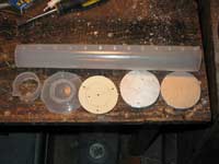
- 1 graduated cylinder with the top and bottom cut off
- 2 small disks of ¼” aluminum plate
- 3 pieces of threaded rod, a couple inches longer than the cylinder – I used ¼-20, which was overkill
- 2 gaskets – I cut them rubberized fiber automotive gasket material
- 9 nylon insert nuts
- 2 brass 5/16” hose barb to 1/8” male pipe thread fittings
- A 1/8” pipe thread tap
- Primer bulb
- About 15’ of 5/16” fuel hose
- 6 hose clamps
I already had the pipe tap, and the rest of it cost maybe $30 and took a couple hours to assemble.
First cut the ends of the cylinder to get rid of the base and the spout. Try to get the cuts reasonably square. I used a regular hacksaw after marking the cuts in ink. Then lap the end of the cylinder on fine sandpaper on a flat surface. It doesn’t need to be perfectly square, but it should be close. It does need to be perfectly flat and reasonably smooth. This “machined” edge is what prevents leaking.

The boring and tapping of the disks shouldn’t give any trouble. The small holes are not tapped. Only the center holes are tapped.
Then you need to cut gaskets. A paper punch is handy for making holes, but you can get it done by sharpening a piece of tubing and using it as a hollow punch. Be sure to get good gasket material. I recommend going to Napa Auto Parts, as it seems they reliably carry the good stuff. The stuff from the hardware store crumbled.
Then you screw in the hose barbs with yellow Teflon tape. (The white stuff won’t tolerate fuel.) These fuel type hose barbs with the stem-and-bulb shape are available at Napa, and probably other good auto parts stores. Hardware stores generally have the one-way sawtooth-ribbed style. These can work, but you really can’t remove the hose without cutting it off in most cases. The fuel type allows a secure grip for a hose clamp, but reasonably easy removal as well.
Finally we wedge it all together with the pressure from the nuts. Tighten them so they compress the plates evenly against the cylinder.
The extra set of nuts on the threaded rod is simply to provide a spot to tie on some light line. I tied a line onto each one and then tied them all together into a loop so the assembly would hang vertically.
Then test for leaks. You should probably filter or discard the fuel you leak test with. There’s no telling what grit will wash out.
Now we need graduations useful to our purpose. First we need a starting point fairly near the top, then we need an ending point or points. Probably the maximum range of measurement for this system is 200 mL. Outside of that range we will either weep fuel out the vent or start sucking air into the bottom hose. If we’re burning two gallons per hour, this equates to 126 mL per minute, or around 1.5 minutes for 200 mL. Burning a half gallon her hour we’re using 31.5 mL per minute. That’s around 6.5 minutes for 200 mL, or obviously half that for 100 mL. I guess 150 mL will cover the range I need. These are easily marked by highlighting the existing ridges with permanent marker.
Graduations
If you didn’t use the graduated cylinder approach, you will need some gradations marked on the jar or tube. Jim did this the hard way by measuring the jar’s diameter, subtracting the plastic thickness and calculating the height of a given volume. But he’s an engineer and that sort of thing comes easily to him. My approach requires no math. Get a syringe from an agricultural supplier or veterinarian. Sometimes you can find syringes meant for measuring outboard oil, which you might want to have anyhow. Apply a strip of tape to the side of your tube and then add water 10 mL at a time and make a mark at each level.
By the way, don’t fill the syringe to 10 mL and empty it. It’s much more accurate to fill to 11 mL, and empty to 1 mL. Or any other pair of numbers 10 mL apart. Just don’t trust the very bottom of the scale.
The size of your jar and of your engine might dictate larger increments than 10 mL. But we won’t use all those gradations anyway. We mark them as above – maybe 50, 100 and 150 mL.
Note that you must do it this way if you have a system with internal hoses taking up space inside the jar. This would screw up any graduations that had been provided, since some of the volume would be used up.
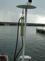
Hang ‘Em High
It is a minor pain in the butt that we need to hang this cylinder above the height of the engine somehow. If you have a bimini, this is easy. If not, just clamp a 2x2 to a bulkhead and mount a shelf bracket on the top. I added a loop to my stern light baffle.
In Use
First you need to fill the cylinder. This is a simple matter of stepping on the primer bulb until enough fuel squirts into the cylinder. Some will leak out the vent if you build it like I did. This would probably be improved by putting two hose barbs on the top and extending the vent upward. I haven’t bothered.
Once it’s filled, I used the squirt tube from my carb cleaner to push in the ball on the hose fitting to let the air out of the hose. I was worried that the float bowl might get fed enough of an air bubble to make the motor stumble or die. There was no stumble at all when switching from the tank to the measuring system when primed as I describe. On the other hand, the air venting might not be necessary at all, assuming the float bowl vent on your carb is clear. (If your motor is slow to prime, it might be plugged.)
Once filled, this system is simple to use. You start a stopwatch when the engine uses enough fuel to cross the starting line, then time it until it crosses the finish line.
Then remember to pump in more fuel so you don’t kill the motor!
Once we have the timed run with a known volume, we do some math. But I hate messing with math on a boat, and calculators don’t seem to like water. So I made a table.
Conversion Table
This is done in any spreadsheet software, and can be modified to your taste to figure gallons per hour at the sort of speeds you typically need to measure. Actually, I’d rather know how many minutes I can go on a gallon, so I express it that way too.
 |
 |
| click the image above to download my table in the format of your choice |
Here’s the really cool part. If you know how fast you were going when you measured the fuel consumption, you can calculate miles per gallon for those conditions using that same spreadsheet. So let’s measure speed.
Measuring Speed
Given the choice, most folks would opt for GPS for this purpose. It is compact, measures instantaneously, and can do all sort of other useful things. But like everything good, it costs. And besides, we probably would like to have a reliable backup. A cheap one.
The Chip Log
The most proven technology for measuring speed through the water is the chip log. It’s been used for hundreds, if not thousands of years. A free-running reel of line is knotted every 23’ 7-1/2”. It is attached to a small sea anchor – the “chip” – that causes it to pay out behind the boat. The number of knots that pay out in 14 seconds is the boat’s speed in knots. After the 14 seconds is up, a sharp jerk on the line releases a pin in the chip so it lays flat on the water for easy retrieval.
The trouble with a traditional chip log on a small boat is that they are bulky and require two people to cast the log. Not so useful for us. But it is possible to address these problems so it can be operated by the helmsman.
I first tried to do this with a miniature version of a traditional chip log. It doesn’t work well at all. Even when using a fishing reel to reduce the fiddling, it still takes more hands than a helmsman can spare. You can’t feel for knots and reel the line in at the same time while also steering the boat. And those knots are too small to count as they are whipping through your fingers as the line pays out. Besides, fishing line whipping through your fingers at 6 knots (or more!) will cause you to find your first aid kit.
Kilburn Adams (The designer of the SkiffAmerica 20) provided the answer in the July 15, 1998 issue of Messing About in Boats. Here it is in brief with a few comments from me:
To do this we need a spincast fishing reel (rod optional), a tennis ball, a piece of coat hanger wire (or large sail needle) and some “no-stretch” fishing line. PowerPro is reputed to be the least stretchy, and cost me $16 for 150 yards of 50 lb line. You’ll also need a watch with a stopwatch function – maybe $15-20 at a box store. If you have good rhythm, counting off the seconds will get you pretty close. That’s what I do.
First wind your reel full of line, since line never pays out as well when the spool is nearly empty. Then mount the reel however you are mounting it, and run the line to the stern of the boat. Don’t forget to run it through the face plate if it’s a spincast reel, and through any guide eyes.
Use the stiff wire or sail needle to thread the fishing line through the tennis ball. Tie it securely. Release the reel and measure off 88 feet of line. (88 feet for statute miles per hour, 101 for knots. Choose whatever your chart is marked with.) Then tie a clove hitch or two on the reel to lock the line there, so no more can reel out. That is your stopping point.
Then there’s a balancing act. Test it out. If your reel isn’t strong enough to resist the drag, try a smaller drogue or a bigger reel.
I found that the release and measurement worked beautifully. But reeling that thing in was a real chore, especially while trying to steer! If there’s wind or anything else making it tricky to stay on course you might have to stop to get it reeled in. Kilburn probably has nicer fishing reels than I do, but I started dreaming of power retrieval.
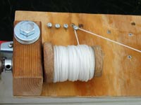
A Power Chip Log
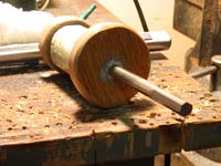
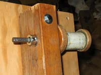
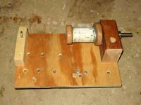
This sounds really fancy but it’s actually easier and cheaper than you would think. The power source is the cordless drill that probably all of us have. Then we need a reel. I wanted some substantial line that wouldn’t snarl up like fishing line, and that I could see in the water. I used mason’s twine, but this begged a larger reel. I made a spool from a scraps of stair rail and hardwood, along with some JBWeld and steel rod from the junk bin. It is hardly a thing of beauty, but it worked plenty well enough to test the concept. The center is pierced by a 3/8” rod, epoxied in. It is worth using a drill press for this, but you can get close enough by eye for this purpose. This rod is plated because I had some in the scrap bin, but stainless would be considerably better.
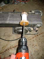 
This rod runs through hole in a piece of 2x lumber, well-greased with petrolatum. Both sides get washers and the shaft is held in place with a collar and setscrew. I filed flats for the collar’s setscrew and so the drill’s chuck could grip.
So now we can reel line in. How do we release it in a resistance-free way? Easy. Turn the whole assembly so it can slip off the end of the spool. So be sure that end of the spool is smooth and varnished. It does need to have that flange, to help lift the twine out of the coil.
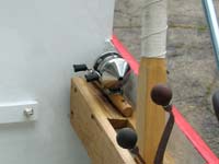
Here’s the bottom view of how it clips to the gunwale.

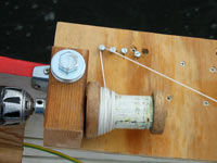
However, I didn’t trust a fisherman’s arbor knot with my smaller outside flange, so I drilled a hole through the spool for truly secure connection of the line. Then I figured an arbor knot would be OK. Note the padeye acting as guide to help the line unspool smoothly.
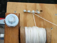
Here’s the really cool part—we don’t need to pivot the assembly to make the spool work in both directions. All we need is a set of wide-headed screws to change which way the line approaches the spool. I used four. First a reel on line near the drill.
Then stop and move the line to the next screw…
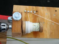
…and so on, ending up here.
The drill motor holds the ball at the ready, but for road transit I put the ball in the motor well and cleat the line.
Be sure to set the clutch as light as you can or you’ll snap the line and lose the ball if you’re not watching the line. I attached this assembly to the gunwale with a ½” bolt through an oarlock and scrap wood cleats that keep the whole assembly from turning.
In use it is the same as the prior version – to make a measurement I flick the line off of the screw. I start timing as soon as the ball hits the water, then stop the watch when the line pulls tight and reel it in before someone runs over the line in a powerboat. Much easier now with power! Then divide 60 by the time in seconds. Remember the spreadsheet above? I provided a table to make this easy.
This is the only version of the chip log practical for singlehanding, in my opinion. Obviously it can be made much prettier that this prototype.
Head Pressure Speed Gauge
Even if you are coordinated enough to master operating the fishing reel chip log, there are times when it’s impossible to use. Like when there are snags or powerboats that will eat a long trailing line. Or when you can’t free up a hand to operate it.
You can also measure speed by measuring the difference between head pressure and static pressure. The instrument is called a manometer and this application comes from an article in WoodenBoat issue #111, pp. 47-50. In this article Peter Compton discusses how to make an inexpensive, accurate permanently installed waterspeed gauge.
I like the idea, but frankly I haven’t gotten around to making one because the power chip log works pretty well.
Knot stick
For another improvement over chip logs, check out the Knotstick. This is a calibrated spring in a plastic tube, with a line that drags a disk in the water. It shares that disadvantage with the chip log – a line dragging in the water – but this one is nowhere near as long. And your speed reading is instantaneous. They go for about $50 new. I’ve seen them on Ebay for $20 supposedly new, but there are no guarantees if you go that route. The Knotstick people have been in business for about 30 years now, so I think you can count on them being around for support. Here’s the truly surprising part – it’s completely made in the USA. It costs more than a tennis ball and mason’s twine, but might be worth it.
Miles Per Gallon
While mph and gph are useful on their own for various things, we can now combine them to get mpg. Again, use the spreadsheet.
So what did I find out? Well, the lakes in Madison are so flooded now that they made everything a no-wake zone, which limited my testing a bit. So the preliminary results are that at slow speed, little above idle, the 18 horse motor burns 1.2 gph. Better than I expected! The rule of thumb of 1/10 the hp would lead us to guess 1.8 gph, and I imagine it will be in that range or a little more at full throttle.
The 5.5 was a surprise in the other direction. At ¾ throttle or so it used .79 gph, which is significantly more than the 1/10 rule of thumb would indicate. However a caveat is that the motor was deeply immersed during this test, even the exhaust telltale was under water! AF4B doesn’t like two motors and me crowded into the stern. This deep immersion may have affected fuel consumption in unpredictable ways.
Speed in both cases was about 4.5 mph, so the big motor yielded a bit under 4 mpg, and the small motor got a bit over 6 mpg. Now suppose the big motor burns two gallons per hour at ¾ throttle, yielding 15 mph reliably. This equates to 7.5 mpg, which is a lot better. But I’ll believe it when I can test it.
These figures were probably complicated by poor trim, but you can see how it could get very important to know them if you want to go a long way where there is no fuel available. This brings up range.
Range
Range might be the best reason for calculating these figures. Even a seasoned mariner like Marlin Bree almost got in trouble when he borrowed a motor that used a lot more fuel than he was used to. (Check your library if you don’t know who he is. Or www.marlinbree.com. Excellent winter reading and a nice guy, too.)
With my six 6 gallon tank I could go about 36 miles with the little motor and only 22 with the big one. Figuring on the “rule of thirds” (1/3 of your fuel there, on third back, one third reserve), this lets us plan a 12 mile trip with the little motor and a 7.3 mile trip with the big one. If we were allowed to make a wake, we might increase that mpg to 7.5 with the big motor, and that would bring the range up to 45 miles, or a trip of 15 miles. Again, I’ll believe that when I can measure it. These things do not always turn out as expected.
Rob Rohde-Szudy
Madison, Wisconsin, USA
robrohdeszudy@yahoo.com
|