Part 1 - Fore Deck Structure
Part 3 - Canvas Decking - Seeking a Viable Alternative to Lead
I had that Cheshire-Cat grin when I read John Bartlett’s BUY DON’T BUILD article here in the great Ducksters’ February editions. My good buddy Nim Marsh is a one-man rescue league for neglected boats who, like John, has found defunct one-design classes a trove of opportunity. He has also passed the trait, by default, to me—therefore he bears the sole blame for a Cape Dory 10 which ended up in a snow drift next to my shop one winter morn and why there are now two of the “Baby Lightening” A.K.A. “Blue Jay” class taking up shelf space here; one, his and his wife’s, of fiberglass, being stored and one, mine, of wood, being re-stored. He and the ever patient Naomi are now neck deep in his latest haul, an lovely old 13’ cat boat, apparently one of three surviving members of Spaulding Dunbar’s Cape Cod Junior class built in Wareham, Mass., in the 30’s. I, of course, am neck deep in my Blue Jay. I’m not complaining mind you, I love boats, either building them or restoring some old timers to health. Just be careful what you wish for…
ARTICLE IV- SPECIFICATIONS, Rule 5. HULL – GENERAL, a: “…Weight of hull at all times and under all conditions, with rigging, mast, boom, rudder, tiller, and centerboard, shall be at least two hundred seventy five pounds (275 lbs.)…”
g. “Side decks must be strong enough to lift boat.”
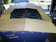
Not gonna happen! The side decks on PLUM CRAZY (ex-CASPIAN) showed significant flex while rowing and could be wiggled by hand along their entire length. No way would I attempt proving IV.5.g!
As was the case with the mast partner and bow structure, old fasteners, original poorly fitted joints and aged wood combined to create a weak understructure.
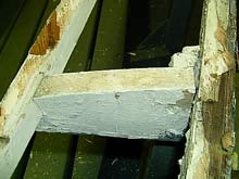 |
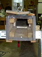
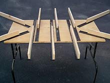
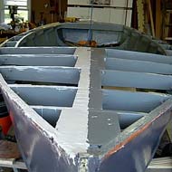
Typical Side Deck Beam |
Sparkman & Stephens’ drawings and the class rules provide scantlings and minimum fastener schedules: the side decks are only 6” wide and roughly 85” long. The beams are thus short sections with some camber (see above photo). The innermost ends of these are notched to receive a ¾” x ¾” cockpit stringer while the outers receive the inwale. Compound bevels (should) apply. By drawing, just three wood screws are used per joint yet all is supposed to suspend nearly three hundred pounds of boat; clearly precise fit and adhesive bedding is required. However, in this 1950’s kit built version all side deck joints, upon dissection, were found dry fit wood on wood with only two screws providing structure.
All this, of course, I didn’t ascertain until having taken delivery; however, the findings bear heavily on the flexing side decks: due to the age and deterioration of the original screws, no structure remained.
So much for exploratory surgery and diagnostics, on with the show…
For this repair I opted for cabosil thickened epoxy, #10 copper rivets and sapele wood for the beams. Following removal of old structure, all was wooded down and (except for glue areas) repainted, fastener holes and any local damage were soaked with epoxy thinned with lacquer thinner, allowed to kick and then filled with Pettit’s Flexpoxy. Split frame ends were soaked, epoxied & through fastened. The new beams were cut 1” longer on the hull edge than shown by the drawings to increase bearing area against frames in order to reach undamaged wood. Beams were got out in pairs (port & starboard at each station, with individual bevels taken on each side) dry fit and glued in with ample clamping and two rivets per joint set.
Cockpit stringer stock was got out of clear cedar, left heavy, steamed, fitted, fastened/glued and planed to appropriate thickness and bevel using a my #6 jointer.
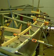
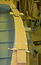
| Clamping steamed stringer to set |
 |
 |
Note set rivets—all joints also bedded in epoxy |
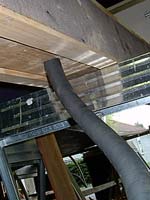
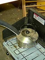
Stringer stock was steamed using the below rig—some specifics on this. This box uses 1 quart of water per hour. Propane bottles, though not fully empty, are changed when pressure drops and flame becomes reduced (about every 45-50 minutes when burning wide open). Time allowances—it takes approximately one hour for box to warm and fill with steam (winter conditions with box starting at ambient shop temps—I usually turn heat on in shop after lighting off the steaming stove. Shop will hang about 40 degrees when warmed). Stock is loaded once steam begins to escape at the loading door. In the case of the stringer stock, two and half hours of steaming induced sufficient pliability that they could easily be handled in my one-man shop.
ARTICLE IV- SPECIFICATIONS Rule 11. DECK. Waterproof fir or mahogany plywood 1/4" thick. Covered with eight (8) ounce canvas or fiberglass, carried down over edge of deck and covered with moulding...
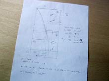
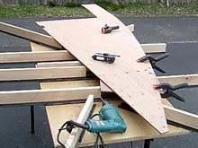
So, decking. Wood is expensive and that particularly includes marine plywood. To my mind allowed waste of 30% materials (a figure told to me by several commercial housing contractors many years ago) is not and never has been acceptable. Back when I did cabinets I made up my own drawings and cut lists & saved considerably on materials. I see no reason why a boat should be any different. Given the size and shape of the deck parts removed from CASPIAN three sheets of plywood would have been required and fully one third of that would have been “scrap”. By employing butt block joints in the side decks, adding a center backing block in the poop, and measuring three times I was able to get everything out of two 4’x 8’ sheets. Transition from bow/poop sections to side decks is based on Glen L, Witt’s Boat Building With Plywood (1978 edition). The below figure shows my final cut list for a 4x8 sheet—all parts for one side.
| One sheet per side |
 |
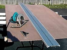
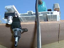
Perhaps this is a good time to mention two invaluable plywood-working tools I stumbled upon. Both are offered by Dino Makropoulos at Eurekazone (Eurekazone.com). The first is the Smart Table, which turns a ¼ sheet of ply into a table large enough to work a 4x8 sheet. The least expensive way to go is to purchase just the top fittings & supply your own legs & wood. The second is the Smart Guide, which effectively turns your circular saw into an accurate panel saw.
 |
Smart Table |
 |
 |
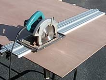
100” Smart Guide and clamp |
Saw base rides along track on guide |
 |
 |
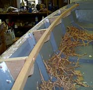
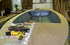
Roughed out deck section |
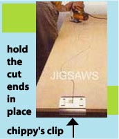
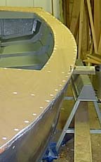
Here the rough-cut panels are laid out in approximate position, each panel was then clamped/weighted, scribed on all sides and for each beam and stringer and then cut to shape leaving ¼” heavy on sides. Pilot holes for fasteners were drilled on 3” centers at same time.
Starboard bow section |
 |
Panels were dry-fit by fully screwing down. Butt joints were made up and all was trimmed to final fit with flush cutter in the router.
 |
 |
Butt joints laid out and glued on one side—these get epoxied during final assembly |
 |
5200 bedding—enough flex to allow woods to swell & contrac |
Underside given two coats of primer and finish coat of gloss white prior to screwing down
|
 |
I will let the cat out of the bag and mention I will be installing canvas covering and had intended to use traditional white lead bedding; however, having meditated on Chuck’s obvious concerns for safety voiced when I first suggested an article on white lead, and the fact I have found some states that prohibit it even being brought across the state line, I decided to research and develop an alternative method--one which won’t result in rotten canvas within a couple years (more about THAT experience later…). There, the cat is loose; stay tuned.
***** |