Posted in October 2007 was an article I wrote about a passive radar reflector design that should perform better than all the commercial units being sold for small sailboats. The impetus for my development was a web report from Sailing Magazine on tests of all the commercial units known in 1995.
As I discovered some months later, my design is not original, since the coast guard has direct “copies” of “my” reflector design marking the entrance to the harbour where I keep my boat! I have no knowledge of any applicable patents, but I can’t imagine any legal action taken against an individual who made one for their own use.
Bigger IS Better
When using a direct-returning “corner cube” (trihedral) shape, the reflected power is related to the fourth power of the linear dimensions of the reflector. I will not reiterate the discussion of the first article except to indicate that the final calculations of the 7-inch-on-a-side design showed that it would be not quite meet the target reflectance in all cases of 2.5m2 RCS (Radar Cross Section). The formula for the RCS of a triangular trihedral on axis is 4.19*a4/λ2 where a is the length of one side of the triangle (about 7" in my first case) and, for X-band radar, λ is about 2.5 cm. That gives a maximum RCS of about 7 m2 for a 7” corner. A little piece of aluminum about 10” on the long edges looks to distant radar like a sphere almost 10’ in diameter!
A final suggestion in the original article was to increase to a 10-inch-on-a-side design. That would give about four times the RCS (since the number goes up with the fourth power of the dimension), so the on axis RCS would be about 29m2. With the 12-degree tip of the trihedrals in my design, the no-heel RCS would become 5 m2 at the transition points and peak at around 10 m2—at least double the target value.
Heeling
A benefit of the larger dimension, beyond providing well over the recommended minimum RCS in all directions when flat in the water, is a better chance of having a big enough RCS when heeled in a wind. As I rethink the question of loss when heeling, I realized the loss is not from ahead or behind—just to the sides. Of course, pitching in heavy seas would be an exception! If one corner reflector is oriented directly to the side (the base rectangle is fastened at right angles to the boat’s orientation), the 12-degree up/down tip of the design will be increased by the heeling on one side and decreased on the other (the reflection drops off to nearly zero somewhat before 45 degrees from the centre axis). Since many engineers (especially retired ones) avoid unnecessary work, I did a web search for a non-geometric way to calculate drop-off in RCS with off-axis angle. Sure enough, scattered in articles discussing esoteric questions of reflector design were just the graph I needed. I’ll spare you the details, but the crude results obtained when using a protractor and a finished reflector assembly are shown in the polar plots below.
 |
click image to enlarge |
When the heel angle gets to 20 degrees, a few points around the perimeter drop below the 2.5 m2 desired (the inner red circle)—still the result is much better than a tiny octahedral. On the other hand, most of the way around the RCS is far greater than the goal. If you are going to sail a steeply heeled monohull, you’d better stay on the lookout for approaching ships. Perhaps you could gimbal the reflectors, but that seems very complicated. Even with this shortcoming, the reflector would be especially useful in a fog when you desperately want big boats to know where you are (and you will not be heeling in a fog!). For night sailing—especially far out to sea—I have not much to offer. I have read horror stories of large freighters that keep a very sloppy watch (even of the Radar screen) when at sea.
Wind Resistance
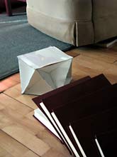
The question of wind resistance has come up in the forum and I have no advice to racers running on the edge. For normal cruisers, my revised reflector assembly represents about a 14” x 10” box at the top of the mast—some wind resistance but not huge. The weight is almost negligible. I might not want to put such a reflector on top a 20’ day sailer, but then I wouldn’t want to take such a boat out in the fog or at night anyway. If I were going to emulate Tinkerbelle, spending my nights at sea anchor, asleep, a little wind resistance would be a small price to pay!
 |
click image to enlarge |
Material Choices
The figure above shows how I would cut the 24” wide flashing to get the necessary pieces. As to cost, the 24” wide aluminium flashing sells for about $2.50 per foot so the aluminium would cost about $12.50. I estimate $2.50 for the pop rivets and assume the top and bottom would be made out of scrap plywood. Some forum comments questioned the use of such thin sheet metal, and I initially had the same concern, but bending heavier sheet stock is quite difficult and gains unnecessary strength. I have no experience for those who would substitute galvanized steel such as is used for heating ducts (I think it is harder to bend) or would make the unit out of plywood and put aluminium foil on with contact cement (one article reported that such a method works well). I am not sure what the minimum thickness must be, but it should be conductive. I think aluminized spray paint would not work well (the binder may keep the metal particles electrically isolated from each other). I put the flashing (which here comes coated with white paint on one side) with the paint side out and have no reason to think the paint causes a problem.
The flashing-weight metal is actually quite strong when the bends have been made and all the pieces are riveted together. I speak from experience because my earlier, smaller unit was at the top of the mast as I lowered it and had my lowering winch slip, letting the top of the heavy mast crash onto the wharf. The reflector was distorted, but not destroyed.
Construction Hints
From comments on the forum, I realize I need to clarify the construction technique:
 |
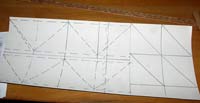
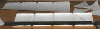
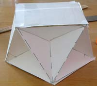
1 - Make all 10 pieces out of some sort of stiff paper so you can easily make folds and get the idea before you mess up a lot of aluminium! Note that the solid lines are cuts while the dashed lines indicate folds. For the paper model, feel free to tape separate pieces together where the fold marks are located if you do not have big enough paper sheets. Mark all the folds with a pencil or pen. |
 |
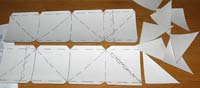 |
2 - With all the pieces cut out, set the 8 small triangles aside and temporarily fold all the tabs over flat forward so they are out of the way. For the small triangles, fold the tabs back. |
 |
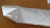 |
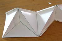
3 - Start folding the strip, making folds back on the diagonals and forward on the verticals. The diagonals should be creased (folded back almost 180 degrees) while the verticals will end up folded forward only 90 degrees (feel free to fold them over flat and then bend them back as needed later). |
 |
 |
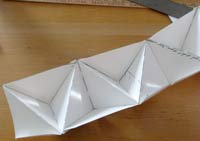
4 - Join the two accordion-folded strips on their ends to make one very long strip (the photos do not show the end tabs since my paper was a little too short and they were left off). Tape the right-end tab of one of the strips to the left-edge of the other strip so it is overlapping |
 |
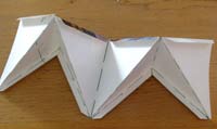
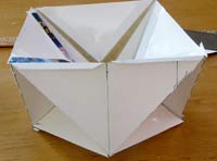
5 - Now bend the side-tabs on the lower edge of the accordion strip back out and tape the small triangles—each to two of the tabs. Then flip it over and tape in the other 4 triangles. If this has all worked according to plan, you will now have 8 corner cubes with each one facing out 45 degrees around from the previous one. |
 |
 |
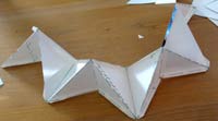
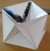
6 - When you have completed the 16 alternating folds and taped in the eight triangles, join the right-most tab of the joined strips to the left-most edge. The strip has now actually come around on itself. I show taping in the last triangle after the two ends are joined. |
 |
 |
7 - Cut two squares the size of the diagonals and fasten one to the top and one to the bottom.
8 -
I find it easiest to do the folds of the aluminium the same way as the paper—it is easier to bend too far and then bend back than to bend short of the final angle and then try to bend more. I would do the pop-riveting as I go along at the same point where I would be taping the paper model. As long as the triangles are cut right, the 90-degree relation of the three surfaces should be quite accurate.
|
Incidentally you can make the entire assembly out of 24 individual triangles (especially if you insist on using heavy material), but you then have to come up with a joining technique for all the edges—my method saves you about 16 joints.
Once you have done this with paper, you are ready to switch to aluminium. I do not recommend anything heavier than flashing because getting in there to make the bends will be very difficult. I find the finished assembly is quite stiff even though the flashing seems quite flimsy. The difference with metal instead of paper is that you fasten the pieces with pop rivets instead of tape. For that, you will need a blind-rivet tool and some rivets as well as the appropriate sized drill (1/8”?) for the necessary holes. While you could pop rivet the top and bottom rectangles to the sides, I suggest you use sheet metal screws instead so you can get access to the interior if you decide to fish wires through from the top (which makes a great place for anchor lights, weather-station arms, radio antennas, etc.). While I used heavy aluminium for the top and bottom the first time, I intend to use epoxy-coated plywood this time.
The biggest challenge I faced in the construction was getting the interior bends in the strips—it is difficult to get some sort of metal edge in there to bend against even though I could almost do the bends barehanded. I think cutting a 14” and a 10” piece of flat steel bar stock might work for the bends. A rubber mallet and gloves might help as well. I even used the edge of a cement block. Once the bend was started right, I could finish it by hand.
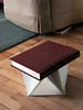
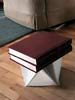
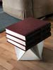
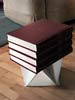
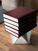
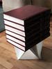
Strength
| Somewhere in the discussion someone questioned the strength of the radar reflector using only thin aluminum. Here is a strength test with light card stock (the kind of paper used for soft cover on paperbacks--the material used for the paper model shown above). I don't know the exact weight but it was significant. The card stock sprang back whereas the aluminum would probably have remained bent. |
 |
Conclusion
All this sheet aluminium bending is a nuisance, but the result looks quite professional to me. After reading how inadequate the units on the market are, especially for their cost, this seems a very economical way to increase dramatically your visibility to any ships using radar.
Tom Schultz
|