Part I: Hull Construction
Part II: Outfitting
Kayleigh : 18' Sharpie Camp Cruiser - Part I: Hull Construction
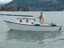 |
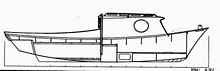
Where this is all headed-the finished boat on
one of her maiden voyages at the 2009 Fern Ridge Wooden Boat
ShOow near Eugene regon. Author/builder at the helm (Photo
by John Kohnen). |
The Kayleigh design has a generous cabin for an 18' boat, and
very clean lines. Specifications are: 18' LOA, 6' 6" beam
and estimated weight is around 600lbs. The displacement hull incorporates
a lot of rocker and tucked transom with a hull speed of around
6 mph with 6hp outboard engine. Designer is Tracy O'Brien https://www.tracyobrien.com
Pretty well into my 70's with an increasingly bad back, I knew
I had to give up sailing. We loved our 18 ' 1972 Baymaster dory
like sloop. But Patricia and I just were no longer nimble or quick
enough to be safe sailors anymore. So we decided to sell "Cayuga"
and find a suitable power boat. I knew this was coming and been
searching for something for the last couple of years.
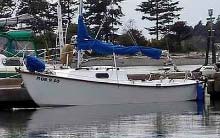 |
1972 18' Baymaster Dory Like Sloop at Sucia
Island in the Puget Sound. Note the similarity of appearance
1between this sloop and the Kayleigh displacement power boat.
(Photo by Author) |
But they just don't make small, traditional type displacement
power boats anymore. I thought about doing a sailing/trawler conversion
from some dry-docked sailboat, but I couldn't find one that appealed
to me. I finally accepted the fact I would have to build what
I wanted. I like traditional designs, needed a good rough water
sea-worthy boat for unpredictable NW rivers and sounds; comfortable
cruising accommodations, economical to build and operate. I finally
narrowed it down to four designs: the Poor
Richard, The Redwing, a 1950's Jackson design called
the "Dolphin," and Tracy O'Brien's Kayleigh. I finally
chose Kayleigh because it met all my requirements and for its
size had the largest cabin space.
The Kayleigh is a sharpie based design with a lot of flare, sheer
and rocker, with a well tucked transom and bottom tumblehome at
the transom ends to avoid her dragging a transom wave, much like
a catboat. In addition the outboard motor is located on a motor
board inside a false transom for protection from steep following
seas/troughs if one gets caught in a mess. Such a hull design,
while 18' LOA, is only about 15' or so on the LWL. So hull speed
is predicted at about 6 miles an hour. This displacement hull
arrangement only requires 2 hp for adequate speed, and 6 hp tops.
Very economical. Tracy's prototype testing was done with a 2hp
British Seagull. The overall construction is a combination of
stitch and glue epoxy composite with longitudinal strip planking
serving as the fore & aft sheer deck beams. A very strong,
yet light weight construction technique.
I ordered the plans from Tracy (~$50) and started studying them.
In my eye the initial design left a few things to be desired:
The cabin, while very generous for an 18' boat was too boxy.
 |
Original design is OK, but I felt the cabin
looked too boxy and foreshortened. |
 |
Author's design modifications |
So I added a brow on fwd cabin top; Bolger "anti slap pad
under forefoot; twin 2" x 6" skegs fwd and parallel
to motor well; cockpit combings; cockpit & cabin top hand
rails; note also the raised motor board. I raised it from 15"
to 18" for further safety from following wash or splash.
A long shaft motor will be used.
The plans called for using marine plywood (fir or mahogany type)
with complete epoxy saturation. I could not find decent fir marine
plywood in Oregon. I was not about to pay $100 a sheet for British
Standard Approved Marine Hardwood plywood, then spend something
like $800 on epoxy to encapsulate it. After a quite complete nationwide
plywood research, I finally decided on Olympic Panel's Crezon
MDO Two Step. This tight lain fir plywood with no voids or overlaps,
sanded both sides and bonded with a phenolic resin paper compound
on both sides. It is used for highway and outdoor advertising
signboards. I talked to Tracy about it, but he feared it would
not machine well for skarfing, etc.
It turned out to machine just fine and took epoxy resin (as in
the the filleted and glassed stitched seams) very well. I bought
3/8" material for all structures except the bottom, which
is 1/2". The cost was ~ $48 a 4' x 8' sheet. As I recall
my total plywood bill was less than $400. The surfaces of this
plywood are very fair and smooth. All that is needed for finishing
is a good paint job. Using this material I figure I saved the
$800 in resin cost and some 300lbs of weight.
For the sheer decks, forward decks, cabin and cockpit hatch and
door framing, I found some rough sawn 4"x 6" x 15' (full
quarter) timbers from Chuck Gottfried, a fellow Coot, from which
I milled all the required parts using a circular saw, band saw
and small planer. The cost of this African Mahogany timber was
~ $200.
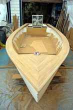
Tracy's plans are very good, they give all the dimensions needed
for the major parts such as the bottom, sides, bunks, cockpit
seats and cabin panels. You have to make up your own plans/dimensions
for the type of doors and cabin hatch arrangement. From the pictures,
you can see how I arranged my portholes, doors, bunks and cockpit
storage areas and seats.
Decisions about helm management determine the door and cockpit
seat arrangement that work best. After some 60 years of amateur
boat building of all types, boating of all kinds, in all kinds
of waters
(lakes, rivers, bays, sounds ocean bars and wide open ocean),
I always go for the simplest arrangement for any system on a boat.
The more stuff you have the more you're asking for trouble. And
no matter what system you have it will fail, and always just at
the most critical time. Therefore I opted for no holes anywhere
in the hull and as few fastenings, pulleys, wires, bolts, eyes,
fairleads, cables, hinges, knobs, electrics, tubes, hoses, blocks,
drawers, or other moving parts as possible.
The stitch and glue method (S&G), done right and carefully
results in a very strong monocoque shell (like an egg) where every
part shares hull stress with every other part with no gaps, frames,
screws or bolts anywhere in the hull to break, pull out, leak
or promote rot.. Putting a hole in anywhere in the hull of a structure
such as this just seems uncalled for. This is not to say that
I didn't use some screws and boat nails in the cabin structures.
For steering I liked the idea that Tracy shows in the pictures
of his prototype, using a long tiller on the outboard. Using a
telescoping tiller extension with a lockable universal type swivel
joint seemed like a good way to control steering and engine speed.
By fastening it to the outboard tiller/throttle you can work both
remotely. Later I will show the shift gear lever extension I made.
With these decisions made I could have the largest area possible
for cockpit seats and stowage, pretty much as the plans show.
The next decision was how to arrange the cockpit doors (all of
these decisions need to be made pretty much before beginning so
you always know where your are going and how you want to wind
up. I decided to have doors that would swing open over the cockpit
seats, flush against the aft cabin bulkhead on the cockpit side,
so I could mount my navigation systems in line of sight, and have
them secure when the doors where closed and locked.
Satisfied I knew generally what I wanted to do, I put up a 12'
x 24" portable shelter with sides in my driveway just outside
of my shop, leaving one end open to the shop for easy access to
my tools. I made a 4' wide by 24' building table in the tradition
of building sharpies, very stout to hold various forces including
my 240lb weight. The sharpies are build right side up while sitting
on their bottom on such a table. The table is made convenient
to a working height considering one must be able to reach inside,
roll the hull from side to side, get in & out, etc. This table
method is an especially easy building using the S&G method.
I bought a $30 Harbor Freight (HF) electric hand planer, made
a scarfing jig for it and scarfed all the bottom and side panels
together.
First, I laid out the bottom on the scarfed 24' long panel, cut
it out and then laid out the sides. Here is where I found a small
error in the plans and proves the use of fairing battens for getting
the proper cut lines. One of the sheer line measurements fell
quite out from the batten line. I checked and rechecked, then
just used the batten line. When boat building, I take the plans
and measurements as base suggestions and ultimately follow the
rule "if it looks good to the eye, its right." I always
stand back from various spots and eyeball everything.
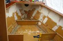
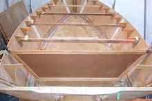 |
Transom, sides and sheer knees S&G'd in
place. The knees hold the cross braces in place during construction
assuring correct hull shape and then serve as supports for
installing the sheer decks P & S and
the fwd deck. (Author) |
The sheer decks and fwd deck are 7/8' square longitudinal strips
scarfed in place using a portable miter box & JAP saw. Forty-five
degree miters are staggered. This a major job and the hardest
part of building the boat. The strips rest on the knees and the
decks are supposed to be flat. But my milling was not 100% square
so I allowed the strips to take their own form and wound up with
crowned decks, which actually added to the appearance and water
runoff characteristics of the structures. An example of the Zen
of boat building," let it be what it is!"
I first started used a slightly thickened epoxy for gluing and
galvanized nails for fastening the strips as Tracy said to do.
This quickly turned into a huge mess, and even though I pre-drilled,
I had bent nails all over the place. I got very discouraged and
had several G&Ts that night. I tried other glues-still a mess.
Finally, I found some ceramic coated deck screws and used Gorilla
Glue. It stayed in place while I screwed around with fitting and
fastenings. When the sheer decks are in, the hull is structurally
basically complete. At this point it could be finished as an open
skiff. This type of design makes for a very rigid and strong hull.
You basically have a composite eggshell with 8" x 1"
I beams longitudinally P&S.
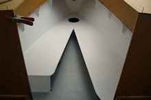
 |
This type of design makes for a very rigid and
strong hull. (Author) |
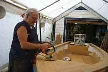
Once the sheer decks and forward deck (same method) I went back
to HF and bought a $30 8" disk sander and packs of assorted
grits, starting with 60 grit. This is a big sanding job, getting
everything fair and nicely shaped. The final sanding was done
with lighter grits using random orbital sanders. I went through
a total of three (one large disk sander and two RO's building
this boat). Sanding is one of the things I hate about S&G
construction.
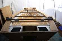 |
Sheer decks done, motor motor board and aft
hatches installed. Author) |
The motor board is fwd of the hatches and is raised to 18' from
the plan's 15". In gives more freeboard to the motor mount
and also provides the lip just fwd of the hatches. This keep drainage
from any motor well splash back into the well instead of into
the cockpit. The cross braces with the "feet" on them
are in preparation to turning the the hull for bottom work. The
hull will rest on the little 2" x 4" feet.
 |
Lots of sanding. (Author) |
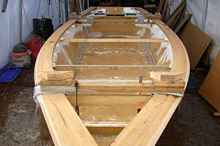
|
Sheer decks and fwd deck finished. Hull structure
is complete at this point (except for bottom work), and could
be fitted out as an open skiff or launch. (Author) |
At this point I gathered a bunch of Coots https://www.coots.org)
together to turn over the hull in preparation for final finishing
of the bottom. This only cost some pizza and French Vanilla Ice
Cream. The actual procedure prior to this time was:
1. Stitch and glue the hull
2. Install knees
3. Install turning braces and feet
4. Turn the hull
5. Finish the bottom
6. Turn the hull
7. Build the sheer decks, fwd deck and topside structures.
Once the hull was turned, the chines, transom, and bow all had
to be beveled and taped. Then the was bottom glassed. I chose
to use Xynol rather than fiberglass for covering the bottom as
recommended by Reuel Parker (The Sharpie Book). Besides being
much more resistant to abrasion and taking in about 1½
times more resin (good for strong bottom), than fiberglass, it
drapes very easily around corners, cuts easily with sharp scissors
and does not leave the "fiberglass itch" when sanding
after saturation. Its about the same price as fiberglass, maybe
slightly more. As per Tracy's instructions I mixed graphite into
the coating resin, along with fumed silica to get a slippery but
very hard surface on the bottom.
There was quite a lot of work to do here, as the bottom is a
very important part of the boat. It must be very strong and resistant
to rocks, logs, beach sand and other abuse. Its characteristics
determine how the boat handles underway, in beaching and at anchor.
I kept all of these functions in mind as I went to work on the
bottom.
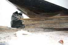
After the bottom was sealed with zynole and epoxy the skegs were
made.
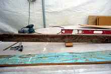 |
A level line from the bow pad was established
and the skeg patterns were made so that the bottom of the
skegs are on the same plane as the bow pad (anti-slap pad)
which will be about 2" deep from the foot of the stem.
(Author) |
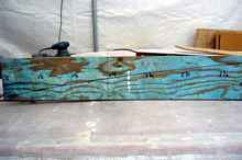 |
Pattern cut station heights are marked at set
intervals along the bottom of the hull. (Author) |
Skeg patterns are made from ¾" scrap plywood. A scribe
line is made by measuring distance/height stations along a longitudinal
line about 5' long the hull fwd of the motor well. The skegs are
made from
2' x 6" pressure treated planks, set in epoxy mush (epoxy
resin + wood flour + fumed silica) and temporarily fastened with
long drywall screws from inside the bottom. The skegs will be
filleted with
1" epoxy mush fillets, taped with 10 ounce x 6" bias
tape, and faired with mush again. The bottom will not receive
its final epoxy/carbon fiber until all these structures are complete..
Its a twin skeg arrangement attached fwd of the motor well and
on both sides. I chose this method to assure adequate steerage
in the wind and to provide a stable platform for drying out on
mud flats and to avoid turbulence in the propeller area (as opposed
to a single skeg along the center of the keel line).
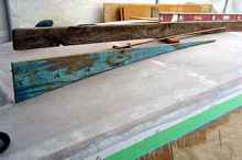 |
Skeg patterns are made from ¾ “
scrap plywood. (Author) |
Once the skegs were made and attached, I made a "Bolger
Anti-Slap Pad." This idea is sort of like a mini "bow
pod" which smooths out ripple "slap" on the hull
while moored or at anchor. I added a small fin like shape to the
very bottom of the anti slap pad to act as a cut-water when going
upwind under power.
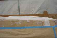 |
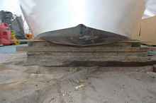
Profile of the anti-slap pad. It is made from
multiple layers of 1/2" MDO and faired with Marine Formula
27. Lots of grinding and sanding here too! Note mini peak
at center of mound. This is to help break wave slapping both
at rest and underway. (Author) |
This shows scale of size of the pad. Its about 30" long
overall and runs from chine to chine and on a continuous arc from
the point of the forefoot. When constructing the hull, I put about
3 or 4" of mush inside the bow, made a 2" x 4"
Port Orford stem that ran from the breast hook area down to the
foot of the bow and embedded it into the mush. With such a reinforced
bow, and then another 2" or so of resin laminated MDO running
30" aft of the forefoot in the form of the anti-slap pad,
I feel I have a very strong bow area in case of hitting any deadheads
etc.
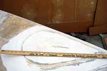 |
This shows scale of size of the pad. A level
reference showing thickness and height of anti-slap pad. (Author) |
I strung a level line from the foot of the bow to the end of
the aft most part of the skegs in order to develop a single level
plane of reference for the bottom of the skegs and the highest
(deepest) point of the anti slap-pad. This is to assure even footing
for grounding in mud flats. It also serves to protect the engine
lower unit, since given the rocker of the hull and the depth of
the skegs the propeller does not extend below that plane.
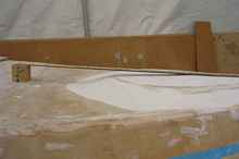 |
A level reference showing thickness and height
of anti-slap pad. (Author) |
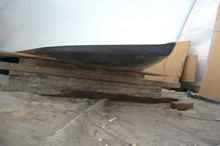 |
Some views of the ant-slap pad from different
angles with the hull in a water line attitude. Did the antislap
pad work? You'll have to wait to Part IV: Performance. (Author) |
Once all the basic hull structures were finished, it was time
to lay out the cabin for sleeping, stowage and galley areas. This
takes a lot of thinking about how one wants to do things; whether
most cruising will be done solo or with a mate, balancing easy
access stowage with floatation, porta potti usage and cooking
in inclement weather.
The first thing was to find a level reference line around the
perimeter of the cabin. The plans give instructions for finding
the waterline level attitude of the hull, so one can be assured
that the bunks and other structures will be level when the boat
is actually in the water. Getting the hull waterline level is
easy, but getting the level reference line around the inside perimeter
is not so easy since there is no place to measure from. I used
a combination of techniques; levels, laser levels and a technique
similar to finding the boot line on the outside of a hull (colored
water in long clear plastic tubing). Each of these techniques
gave a different line! So I kind of battened/level lined the final
reference line as an average of all the others.
 |
After establishing a level cabin interior perimeter
line, longitudinal cleats are installed to notch in bunk bulkheads
and provide base for bunk tops. (Author) |
Forward of the fwdmost bulkhead under the fwd deck is another
bulkhead bonded to bottom, sides and deck. This will be a watertight
floatation/crash area which is further protected by a 2"
x 4" (full quarter) Port Orford stem embedded in a generous
layer of mush. Just fwd of that wider bulkhead will be another
floatation area with an inspection plate. I store extra butane
fuel and water bottles in here as it is both water tight and accessible.
 |
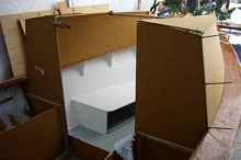
All the bunk bulkheads are installed, as is
the fwdmost top to the fwd floatation area. (Author) |
The port bunk is shorter to allow the porta potti to fit just
aft of the bunk. Prior to deciding where to put the bulkheads
(and therefore the bunk tops), my wife and laid down in the bare
hull and we drew our supine body outlines on the floor to assure
adequate bunk space for sleeping. Actually this accommodates two
6' adults. The longitudinal strips on the floor are 1" x
1" oak epoxied in. I did it this way to allow sliding galley
and other stowage boxes under the bunks (as opposed to installing
longitudinal bulkheads). When the bunk tops are boat nailed and
epoxied in place, it completes the structural integrity of a monocoque
effect with the hull (sides and bottom). There are no frames in
this type of construction and no joints to come apart and rot.
It's easy to keep clean. The only downside to this method is dealing
with the epoxy (sticks to everything in the shop) and all the
fairing/sanding.
 |
View of the bunk bulkheads looking aft. Note
the water barrier between the cockpit (where the porta potti
is temporarily resting) and cabin area spanning the space
between the port and starboard sides of the aft cabin bulkhead.
It is 8" high. (Author) |
 |
Bunk tops installed. All the cabin interior
work is done before the actual cabin is installed. Note potti
space on aft end of port bunk. (Author) |
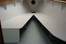 |
Another view of bunks, floatation and stowage
areas. (Author) |
Either bunk is long enough for one person to sleep at either
end since one can have their head clear forward under the forward
deck, or two with their feet toward the bow. Berth tops are ~
22" wide. Note the curved in area on the aft end of the std
bunk. The bunk is wider than the cabin door will be, so this is
needed to allow ease of entry. The 12v deep cycle battery will
be placed under the aft end of the stb bunk with a hatch above
it for service and connector access. Aft cabin bulkhead, cabin
sides and top were temporarily set in place to be sure there was
adequate real time space for sitting head room, potti access,
stowage access and interior cabin movement allowances. I never
depend on measurements alone. I always put a human body or other
object of use in the space I am building to be sure it all will
fit and be usable and space efficient.
 |
Aft cabin bulkhead, cabin sides and top were
temporarily set in place (Author) |
Next is figuring out the dimensions of the cockpit hatches. The
cockpit is ~ 6' long from the aft cabin bulkhead to the motorboard.
The cockpit seats will be ~ 11" high, with plenty of room
for good sized hatches.
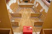
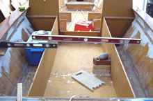 |
Cockpit seat longitudinal bulkheads are temporarily
fitted and leveled P & S. (Author) |
Note cooler is placed where I intend to use it to be sure there
is adequate room for it before taping and gluing in the bulkheads.
A level perimeter reference line around the outside of the cockpit
is first established using levels and the waterline boot trick
mentioned above. Splines are sort of fitted to an average of all
the resulting marks and the level line is drawn in. Cleats are
then fastened around the perimeter to assure P & S level reference
for the tops of the seats. The main parts including all the main
bulkheads are cut from dimensions given in the plans. All the
bulkhead parts are from 1/2" MDO, as are the berth and seat
tops.
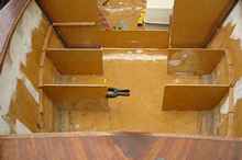
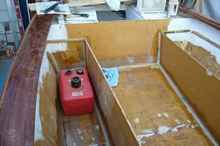 |
Looking aft, the cockpit longitudinal bulkheads
have been filleted and taped in. (Author) |
The fuel tank is temporarily put in place to assure plenty of
room for stowage and access. Since this hull only requires a 6hp
engine, I use 3 gallon tanks which are small and easy to joggle
around. I have four of them (usually only carry two), one in each
hatch P & S. Cutouts in the bulkheads will be made later to
access the tanks.
Next time I will show how the cabin is put together, along with
some of the hatch details and finishing techniques.

***** |