| Part One - Part Two - Part Three
Part Two
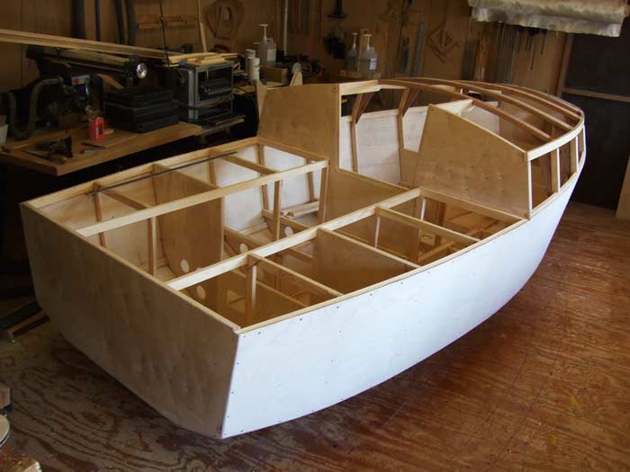
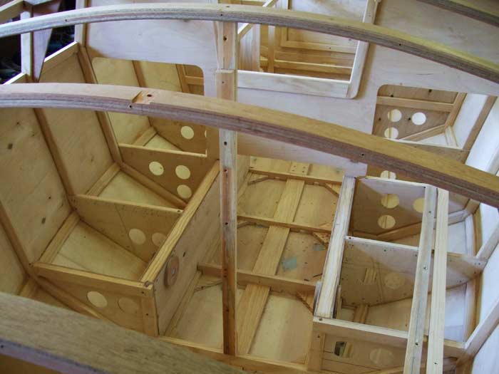
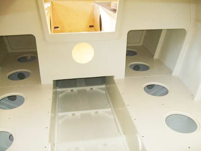
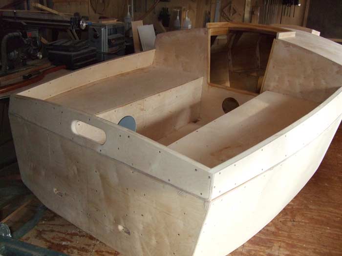
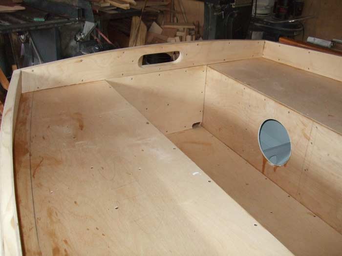
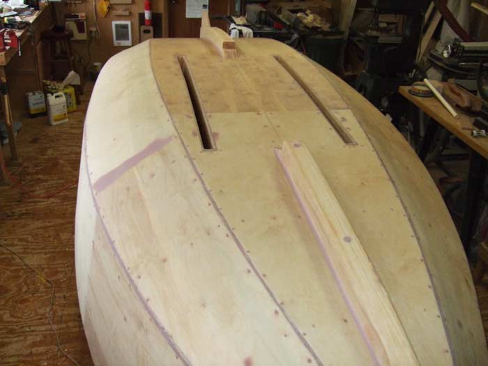
One unique feature of this design was that it was shown with two centerboards with each case forming the front of the bunks in the cabin design. This allowed better space in the cabin by not having the case in the middle of the cabin itself. It also allowed the opening in the top of the cases for lifting the boards to be used for cockpit drains in the self-bailing cockpit.
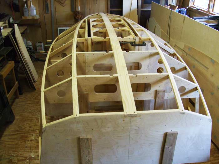
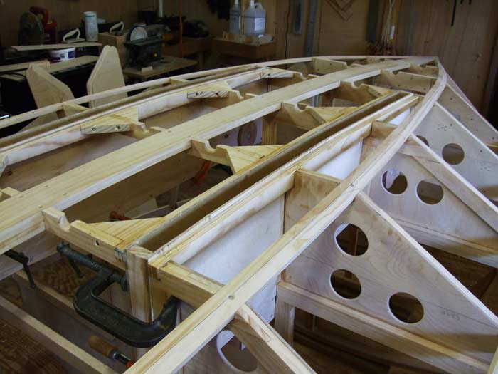
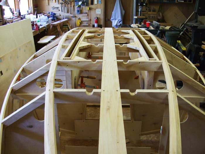
The cases were constructed and glassed completely and installed at this time. At this point all the stringers were in place and planed to the shape to accept planking with 6mm plywood. The frames themselves were shaped for fair planking and all limber holes and reinforcements completed. I made sure that things that needed to be done were complete as it would be extremely difficult to do after the planking was on.
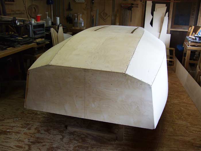
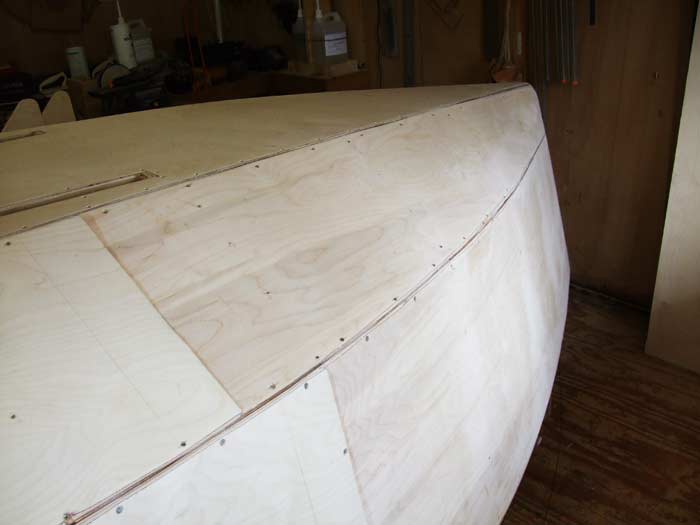
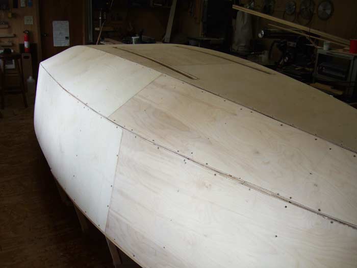
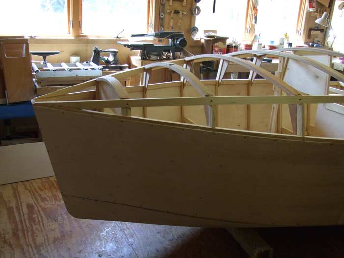
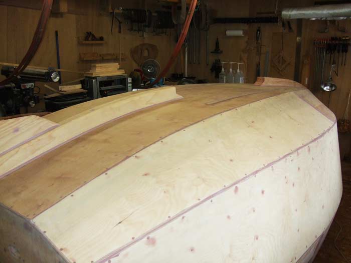
The time had now come to transform the complete skeletal frame into a boat by planking with 6mm plywood. The 4'x8' plywood panels were scarfed together to avoid using butt joints. All the planking was fastened using epoxy glue and stainless screws.
With the planking complete, the boat was rolled over in the shop using a system of nylon straps as slings allowing the boat to be rolled completely contained in the slings. Another good reason to build small boats is I can, by myself, completely lift and roll over the boat.
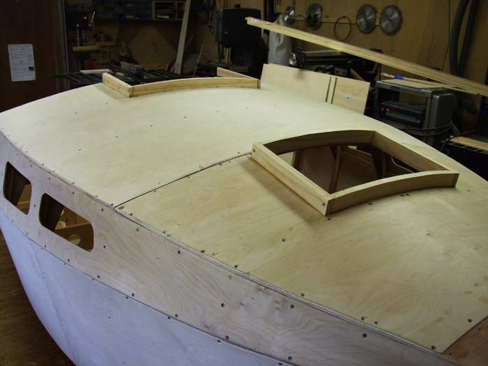
Now, with the boat upright I could begin the work of completing the cockpit, cabin and decks.
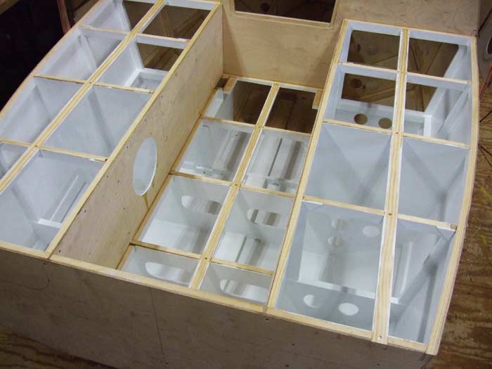
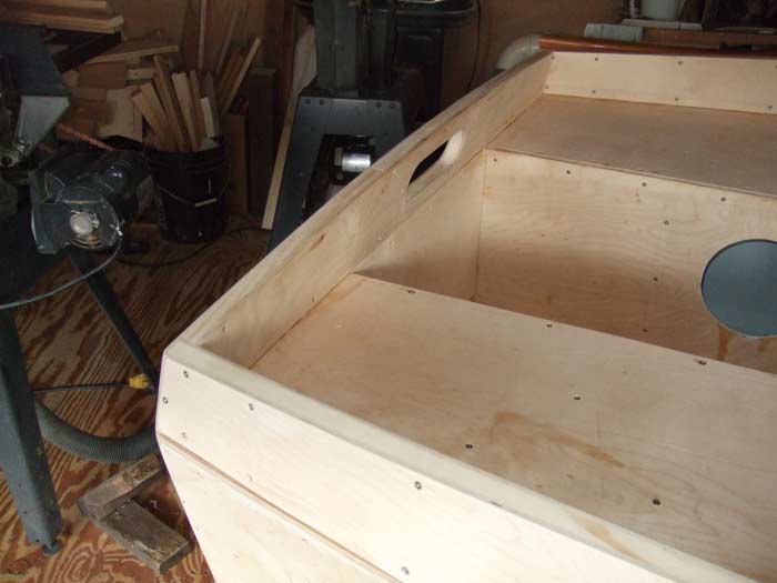
You will note that holes were cut into frame sections to allow air movement and ventilation in closed spaces within the boat. Good ventilation I believe helps to prevent moisture buildup in these spaces.
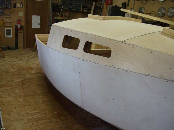
The cabin sides and deck-cabin top were now completed and the main and front hatches were framed in place. The design also showed a small anchor locker at the bow which was also completed. This locker would be sealed from the rest of the boat and would have drains overboard.
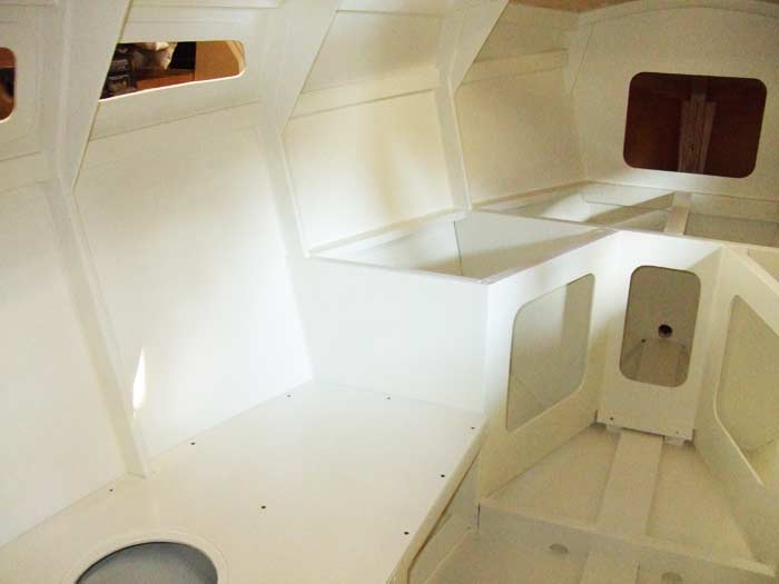
I decided to paint the interior while it was still accessible. You always want to keep advancing with the construction, but it is wise to stop and do things like painting before it would be impossible or extremely difficult. The one part of painting that I have always hated is the painting of the overhead structures, but in this case I once more used the slings to roll the boat over and now could paint everything quite easily.
The original plans called for only a partial coaming around the forward part of the cockpit which I did not like. I constructed a complete coaming around the entire cockpit including the transom. The self-bailing feature of the cockpit shows drains in the transom and if you look close you can see one of the forward drains that is actually the exit lift opening for raising the centerboards. This allows the cockpit to drain thru the centerboard cases.
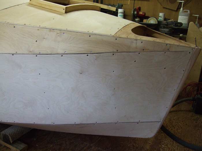
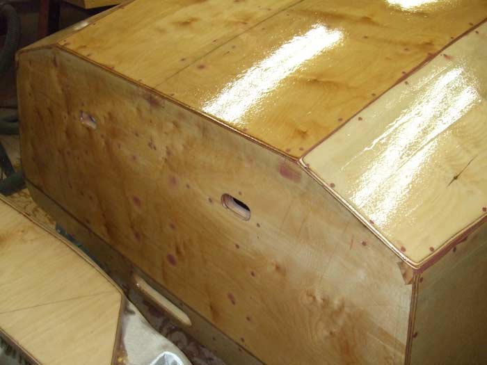
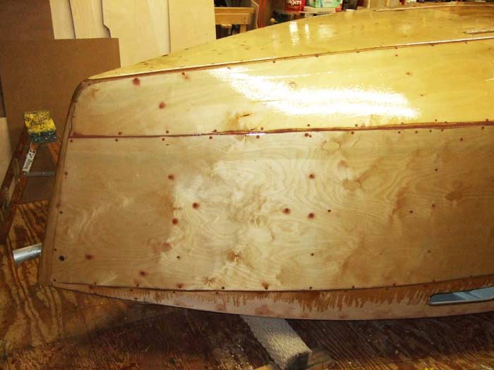
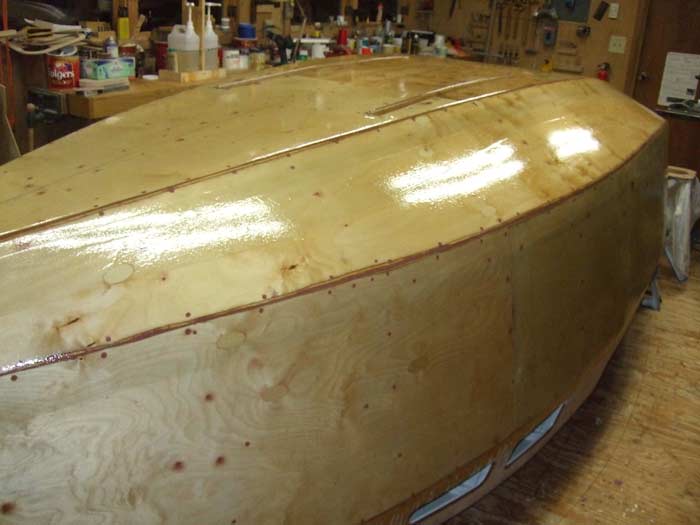
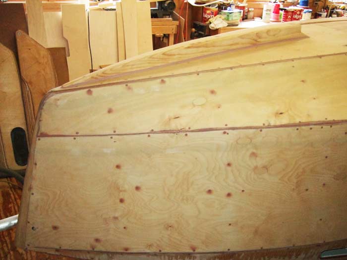
All the screw holes and gaps between the paneling were filled with epoxy filler. The edges and corners were rounded and the complete boat was sanded. The next step was the complete glass cloth covering of the entire boat with 10oz cloth and epoxy resin. The schedule was to have two layers on the bottom and one layer on all other surfaces. The epoxy resin was rolled on in at least four coatings.
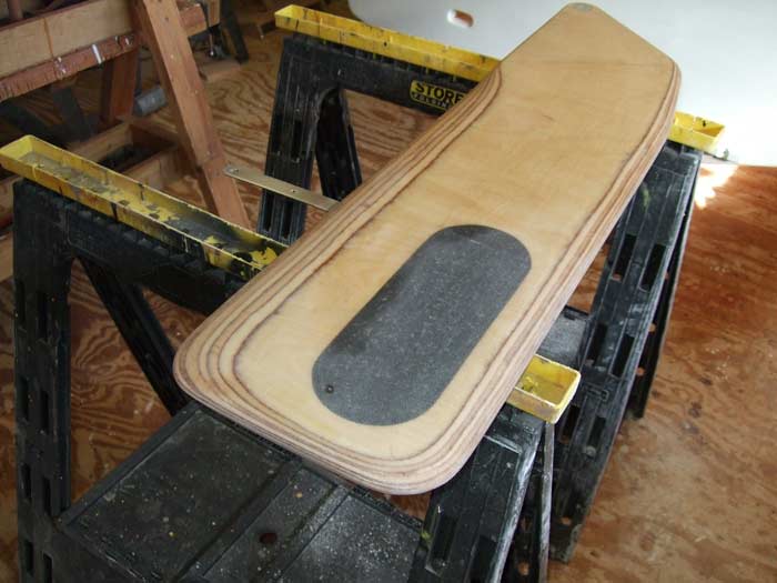
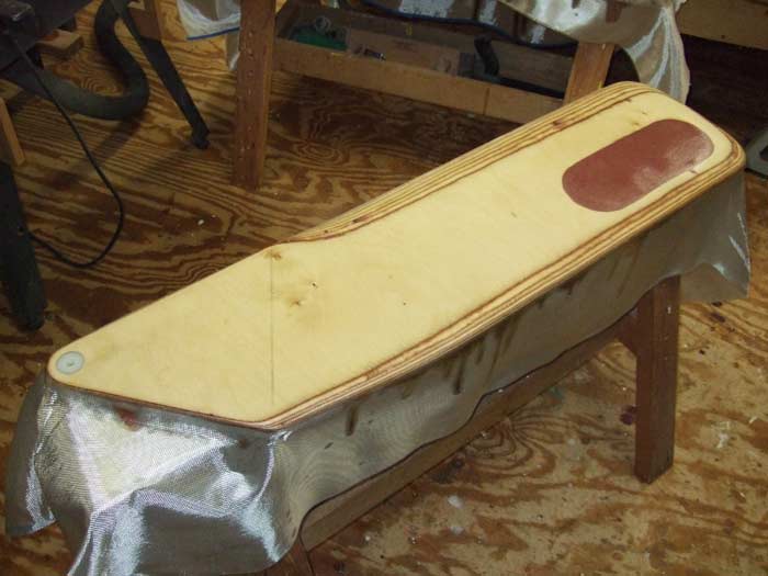
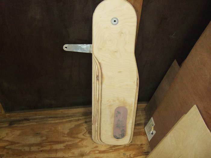
After all the work of glassing I took the time to build and finish the centerboards and the rudder blade. They were weighted by using lead birdshot mixed with epoxy and poured into openings cut into the blades. About 20lbs per centerboard and 12lbs in the rudder blade.
The design plans called for approximately 170lbs of lead ballast in the bilge inside the boat. I did not like this arrangement and decided to find a way to add the lead as outside ballast. The original design called for 2"x 2" skeg down the centerline of the boat. To accommodate the space needed for 170lbs of lead, I increased the skeg to 3"x 3" and left a gap in this skeg to allow for a casting of this weight. The front to back position was determined from the location of the designed inside ballast. The skeg was dramatically tapered forward and had small blade added to the after end.
Next time: Paint and go sailing
|