|
BOATBUILDING WITH A DIFFERENCE III
(For Aspiring Amateurs)
by Barend Migchelsen
Migchelsen@aol.com
https://ca.geocities.com/bmboats2002/
https://members.aol.com/_ht_a/migchelsen/myhomepage/
|
Barend Migchelsen, (pronounced Mikkelsen) learned to sail in The
Netherlands in 1943. In 1975 he started to build boats and boat models as
a hobby. Today, he organizes and teaches classroom courses in boat
building, and has published several books on the subject. The
following is an excerpt from one of these books.
Click here to check
out Barend's books at our store
|
|
STEMS
The meeting line fore and aft of the side panels of a
Double-ender is not just a curved line; the angle between the panels
varies from the sheer diminishing downward to the heel of the stem.
Its Profile view is shown in figure 3-1.
It makes construction of stems difficult for a new amateur who has
only beginners luck on his side. |
|
Fig. 3 - 1
The curved stem
has a varying crosscut angle.
The degree of variation over the whole stem can be
easily calculated, but it is a waste of time and effort unless you insist
on a curved stem.
Side Panel Modification
From station #2 forward, and from station #14 toward
aft, the side panels are no longer bent, but are allowed to continue in a
straight direction as tangents to the sheer line circle segment.
Instead of coming together at station #0, the sheer
lines join each other five inches
fore of station #0 at the location #0-5", and
aft at station #16+5".
This increases the Overall Length of the hull to
LOA = 16', 10".
The angle that the tangent lines make with the
centerline is equal to the bevel angle of cross frame #2 (and #14), which
is equal to the angle of the center point angle between the radii R2 and
R8 (= the angle between R14 and R8).
That angle is
22.24 degrees.
See figure 3-2. |
|
Fig. 3 - 2
Side panels
tangent line
Allowing the side panel to continue as the tangent
line to the sheer line arc delivers two important simplifications:
1.
The stem becomes straight.
2.
The bevel angle of the stem, called the crosscut angle becomes
constant.
What was the most difficult part to construct becomes
one of the easiest to cut, especially for the beginning amateur with
limited, or no carpenters skills at all.
SAC (Stem At Chine)
In figure 3-3, the Body view, the (maximum) bottom
rocker between Beam and the heel of the stems is three inches.
The location where the two chine lines join the heel of the stem I
call Stem At Chine.
For easy writing, abbreviated to
SAC.
The location of Station SAC on the centerline is between stations #1 and #2.
See figure 3-1. On the sheer line in the half-Body view of figure 3-3 that
location is
hsac = 22 x sin 22.62º = 22 x 0.3846 = 8.46.
The exact location on the centerline of the station
line SAC in Profile and half Bread view can be calculated with the
formula:
hSAC + (R - hBeam) = v(R2 - dsac2), or 8.46 + (190.23 - 26) = v(190.232 -
dSAC2)
in which
dSAC
is the distance between station SAC and
station Beam (station #8).
Worked out,
dSAC = 79.785",
or the location of
station SAC
=
station #1 + 4.215" as is shown in figure 3-1, and more detailed in
figure 3-4. In this
illustration the original curved stem and the sheer line the Profile and
half-Breadth view are drawn in red.
The exact length, and the rake angle of the modified
stem in black lines are written in.
Also shown is how one half of the
constant crosscut is determined
in this to scale drawing.
When the drawing is made on
one-inch-grid graph paper a high degree of accuracy is achieved, even
if it is done on a one-quarter scale.
It makes the rest of the Profile and half-Breadth views redundant!
All the important values of the measurements are written in.
The mathematics is just Pythagoras and the basic
trigonometric definitions of Sine, Cosine, and Tangent applied.
It is all junior high school
stuff. If a check of the
accuracy of figures of these measurements gives you any difficulty, just
send me an email for clarification. |
|
Fig. 3 - 3
Half- Body view
of the Double-Ender
In figure 3-4, one-half of the crosscut angle is
31 degrees. A 2"x3" ripped
diagonally gives two right-triangular slats. The tangent of the angle between the hypotenuse/cut and the
2½"-long-leg side is
1½/2½" = 0.6. The angle is
exactly 31 degrees!
Place the two 2½" sides of the slats back to back.
Cut the rabbet groove.
Miter the stem at
46 degrees. In The
Netherlands, where I was born, they say:
Even a toddler can do the washing.
See figure 3-5.
With the modified sheer line, the straightened-out
stem, the raked tomb stone, or transom board, the increase of the Overall
Length, the added guardrails and their capping, varying flare and the
quoting of the outside
measurements, it becomes more difficult for the untrained eye to recognize
the original Double-Ender design from which the hull is developed. However, it is still there!
But the most important result
is that even a person with two left hands can now build the simplified
boat. |
|
Fig. 3 - 4
Profile and Body view
of the modified stem |
|
Fig. 3 - 5
Stem made from diagonally ripped 2"x3"
Skiff
In a 12-ft Skiff the building of a hull is further
simplified by replacing the difficult-to-make stem aft with an even
easier-to-construct transom board.
A vertical transom board does not need any
modification of the original sheer line circle arc. The bevel angle of the board equals the center angle between
the radii R12 and R8 (Beam).
The distance between station #12 and station #8 is
d12 = 48".
The sine of the center point angle is
Sin CP-angle = d12/R = 48/190.23 = 0.252326. The center point angle is
14.6
degrees. The tangent of that
angle is:
Tangent 14.6º = 0.26. Make a
right triangular template from a piece of scrap plywood.
The long leg is
10";
the short leg is
2.6". Set
the short leg on the table of the saw.
Adjust the blade against the hypotenuse.
Cut the bevel on the side of the transom.
I never bother to draw a transom, but take its measurements
directly from the setup. It
is foolproof.
Raked Transom
Besides the fact that it makes the boat roomier, a
raked transom improves the beauty of the lines of the hull.
If the rake places the top edge of the transom between the sheers
at station #13, the sides of the transom board require the
difficult-to-make varying bevel
angle. This difficulty is
eliminated in the same way as with the stem fore:
From station #12 toward aft, the sides are allowed to go straight
in the direction of the tangent to the sheer line circle arc at station
#12. The varying bevel of the side edges is now the same constant
bevel of station #12 which is
14.6
degrees. It adds at the most
1½" on each side at the width of the transom board between the sheer lines.
The width at the bottom at station #12 stays the same.
Especially with a raked transom, take measurements directly from
the setup.
FLARE
With flare, the bottom half of the boat is narrower.
Resistance when going through the water is reduced, the boat is
more stable when heeling, and the beauty of the lines of the boat is
enhanced.
Modern built dories all have varying flare.
But classic Dories, and the original Double-Enders from which
they were developed have constant flare. Flare
can vary between zero (0) degrees (no flare) to the maximum (Dory) flare.
A hull with no flare at all is very easy to construct, but they are
slow, and, IMHO, look like overdue pregnant bathtubs.
They can also be dangerous when heeling.
When we speak of
flare,
we actually mean flare ratio. In figure 3-3
the flare ratio is
6.25/15 = 0.416667.
The same ratio is shown in the right triangle of the sheer
line/hypotenuse with the half-Breadth long leg and the Profile height
short leg. The ratio here is
the same
10/24 = 0.416667.
In a constant flared hull
the flare ratio is always
Profile height/half-Breadth.
In most of the designs of hard-chined hulls, the
constant flare ratio lies
between the ratios
6/24 = 0.25
minimally and
14/24 = 0.583333 maximally.
The flare angle lies
between
14 degrees and
30
degrees. The reason why the
ratio
10/24 was worked out is that with a constant half-Breadth of
24", the number
10" is
exactly in the middle of the series
6, 8, 10, 12, and 14
for the Profile
height figures. See the table
at the end.
It is easy to understand that when you make your own
boat, you have a lot of choices. The
ratio
6/24
provides a roomier cockpit on a wider bottom with less tenderness than the
ratio
14/24 which produces a faster boat on a narrower bottom.
The choice is yours. Your choice depends on what you want to do with the boat,
where you are going to use it, and any other personal preferences that you
may have.
Without a heavy load the Dory is very nimble.
Windage takes a big easy grip on the hull.
Good tracking is difficult without a skeg or keel.
The rowing position is awkward.
It requires either long oars, or the handles of the oars that are
right under the chin of a crewmember of average size.
The same
characteristics that made her an ideal fishing platform in the wide ocean
become disadvantages for the purpose of leisure boating in less open
waterways.
The first modification would have to be reducing of
the width of the side panels to provide a wider bottom, and a roomier
cockpit. The second change
has to be the attachment of a keel beam with a skeg.
This improves tracking.
Both modifications make rowing easier and make the boat more
suitable for the installation of a centerboard in a box and the rigging
for sailing.
One more remark about this:
Whatever the modifications over time, the flare angle of the
original design can always be found at Beam.
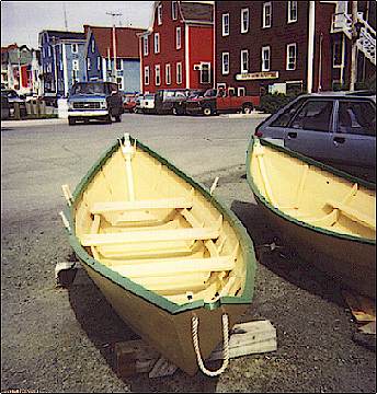
Even in varying flare Dories and the Double-Enders from which they
are developed. See the Dory
picture.
To stay on the subject: Dories are designed as fishing platforms; sturdy boats that
stayed afloat under nearly all circumstances.
Their high sides give support to a bending-over fisherman trying to
grab the lines of the catch.
The boat can take a heavy load.
They are easily stacked aboard of the mother-ship/schooner.
The lack of a keel and a skeg let them drift gentle at the fishing
lines. The beauty of the hull
lines was, IMHO, an accidental quality.
Local weather and water conditions account for the
change of constant flare into varying flare. This gave more accent to the
fine cods head; mackerel tail
shape of the modern dories which is visible at the bottom.
The sheer line amidships did not change, but the side panels fore
and aft were allowed to follow the straight tangent line. The curve in the bow stem became less pronounced and is
easier to make because it diminished the varying bevel of the stem.
So was the bevel of the sides of the tombstone.
With these small changes, the development of the Dory shape had
reached the end of the line.
See the photograph of a new Lunenburg Dory beside The Dory Shop at the end
of the wharf of that city.
The Dory flare
angle is exactly
33.69
degrees, or
33º, 41', 24". I
picture the raised eyebrows and the big question marks in your eyes.
At first sight it looks likes
an extremely odd figure.
In realty it makes as much sense, and it is as easy to construct as the
3",
4", and
5"
carpenters triangle. Make the
long leg of a right triangular plate
3",
and the short leg
2". (Making the template legs
6", and
4" is
easier). The flare ratio of
the Dory is
2/3 =
0.66667. The angle between the hypotenuse and the
3" long leg is then exactly
33.69º = Dory flare angle.
The pronounced flare angle contributes strongly to the beauty of
the Dory lines. I have
serious doubts if even Don Elliot is aware of this Dory characteristic.
If you are still
not convinced: Check the
flare angle of the Beam cross frame of the official drawing of the Lovell
Dory. |
|
The
flare ratio = 2/3
was a (unconscious?) stroke of genius.
It made the setting up of the frames for the classic constant
flare extremely easy and accurate.
I have spoken with several professional Dory builders who were not
aware of this characteristic.
The older ones had received an elementary school education only, or,
forced by bad economic conditions, even less.
Sometimes, they were more real artists than simple boat-builders
anyhow.
THE SYSTEM
In the first article of this series, it is shown that
all other hard-chined, constant flared hull forms easily can be developed
from the original drawing of the Double-Ender, and the formula:
Tan Flare Angle = Profile
height/half-Breadth.
Calculating the radius of the sheer line circle arc
segment provided the key, and became the basis for determining all the
other measurements of a hull.
With the printed tables found here, that information is at your
fingertips. No need to make
the calculations yourself.
The first table provides the radius R for all the
flare ratios from
1/24
up to the maximum Dory flare ratio
16/24. The second table is the calculation of the locations of the
station lines on the hypotenuse/ sheer line in the Body view for the most
common flare ratios from
6/24
up to
14/24. The use of the tables
will save you a lot of time and effort.
Table of the
Calculations of the radius R for the Different Flare Ratios
The mathematical
equation for the radius
R is:
2 x hBm x R = (½ LOA)2 + hBm2.
|
Prfl
Hght
(inches) |
Flare
Ratio |
Flare
Angle
(degrees) |
hBm
(inches) |
hBm2
|
(½ LOA)2
+ hBm2 |
Radius
(inches) |
|
0 |
0 |
0 |
24.00 |
576 |
9216 + 576 |
204.00 |
|
1 |
1/24 |
2.39 |
24.02 |
577 |
9216 + 577 |
203.85 |
|
2 |
2/24 |
4.76 |
24.08 |
580 |
9216 + 580 |
203.40 |
|
3 |
3/24 |
7.13 |
24.19 |
585 |
9216 + 585 |
202.60 |
|
4 |
4/24 |
9.46 |
24.33 |
592 |
9216 + 592 |
201.56 |
|
5 |
5/24 |
11.77 |
24.52 |
601 |
9216 + 601 |
200.22 |
|
6 |
6/24 |
14.04 |
24.74 |
612 |
9216 + 612 |
198.63 |
|
7 |
7/24 |
16.26 |
25.00 |
625 |
9216 + 625 |
196.82 |
|
8 |
8/24 |
18.44 |
25.30 |
640 |
9216 + 640 |
194.78 |
|
9 |
9/24 |
20.56 |
25.63 |
657 |
9216 + 657 |
192.60 |
|
10 |
10/24 |
22.62 |
26.00 |
676 |
9216 + 676 |
190.23 |
|
11 |
11/24 |
24.62 |
26.40 |
697 |
9216 + 697 |
187.75 |
|
12 |
12/24 |
26.57 |
26.83 |
720 |
9216 + 720 |
185.16 |
|
13 |
13/24 |
28.44 |
27.30 |
745 |
9216 + 745 |
182.44 |
|
14 |
14/24 |
30.26 |
27.78 |
772 |
9216 + 772 |
179.77 |
|
15 |
15/24 |
32.00 |
28.30 |
801 |
9216 + 801 |
176.98 |
|
16 |
16/24 |
33.69 |
28.84 |
|
832 |
9216 + 832 |
174.18 |
Flare ratio table for a hard-chined hull of a
Double-Ender:
LOA
= 16 ft.
|
The underlined
figures in the table are the measurements of the Double-Ender described in
this chapter. On the same
side panel width, the flare ratio figures above the line make the bottom
wider. The figures below the
line will make the bottom of the boat narrower.
This ratio table saves you the trouble of having to make the
calculations yourself.
Offset Table of Profile Heights and Half-Breadths
In general, the
designs of most constant-flared, hard-chined hulls have a flare ratio
between
6/24 (¼)
and
14/24 (7/12), or a flare angle between
14 (14.036)
degrees and
30¼ (30.256) degrees.
With this in
mind, the plotting table for the actual sheer line arc, and the
offsets of the Profile heights, and
the half Breadths at the different stations is a great time and labour
saving tool.
The table is
based on the sheer line circle segment of the
16-feet
double-ender. The Profile
heights at Beam vary from
6 inches to
14
inches on a (constant) half-Breadth width of
24
inches. It lists the Body
view measurements of the hypotenuses
hn of the sheer line circle arc at the stations #2 = #14, #4 = #12, #6 =
#10, and station #8 (Beam).
½ LOA = 96". The
distances
dn
are between each station and station #8 (Beam)
All the
measurement figures in the table are given in inches.
The mathematical
equation is
hn = v(R2 - dn2) - (R - hBm).
|
Flare
Ratio |
R |
hBm |
h6
h10
d = 24 |
h4
h12
d = 48 |
h2
h14
d = 72 |
|
6/24 |
198.63 |
24.74 |
23.29 |
18.85 |
11.23 |
|
7/24 |
196.82 |
25.00 |
23.53 |
19.00 |
11.36 |
|
8/24 |
194.78 |
25.30 |
23.81 |
19.23 |
11.50 |
|
9/24 |
192.60 |
25.63 |
24.13 |
19.55 |
11.67 |
|
10/24 |
190.23 |
26.00 |
24.48 |
19.84 |
11.85 |
|
11/24 |
187.75 |
26.40 |
24.91 |
20.16 |
12.04 |
|
12/24 |
185.16 |
26.83 |
25.27 |
20.50 |
12.26 |
|
13/24 |
182.44 |
27.30 |
25.71 |
20.87 |
12.49 |
|
14/24 |
179.77 |
27.78 |
26.17 |
21.25 |
12.73 |
|
The underlined figures are the measurements of the
Double-Ender model constructed in these articles.
The Flare Ratio Table on the preceding page, and the
plotting table for the heights of the sheer line circle arc segment above,
eliminate the need to make any calculations.
Plot the dimensions on one-inch-grid graph paper.
Draw the hull lines completely in Body view.
Instead of the 10" Profile height at Beam as found in these
articles, change to the Profile height of
your choice, which can be any
number between
6
inches, and
14 inches.
If you want to build a bigger boat, based on an
18', or
24'
Double-Ender, just increase the scale of
all the measurements by the
factor
1½, or
2. It is that simple with
this mathematical system of design.
SIDE PANELS
In the half-Body
view of a Double-Ender, figure3-6A, the chine line is drawn parallel to
the sheer line. The side
panels have the same width over the whole length.
The rocker from the Beam to the stems is 7.4".
Station BAC (Bow At Chine) has moved forward
to station #1 + 0.655. The
chine lines in Plan and half-Breadth view run parallel to the sheer lines.
This strong rocker is still visible in the McKenzie-River Dories. |
|
Fig. 3 - 6
Chine lines
parallel to the sheer lines
Cods Head, Mackerel Tail
In figure 3 -7A, the original chine lines parallel to
the sheer lines are the dotted lines.
In this drawing a new chine line is drawn in red.
Instead of a rocker fore of Beam of 7.4", this rocker is reduced to 3", a difference of
4.4".
At the same time the rocker
aft of Beam is increased by the same amount of 4.4.
The bottom is no longer parallel to the (horizontal)
plane of the two sheer lines, but tilted from fore to aft as shown in the
Profile drawing of figure 3-7B.
Although the sheer line
itself has not changed, the bow has become substantially higher. (or
should I say the bottom fore deeper?)
In Dories this is not so pronounced as in the Punter, but still
clearly visible in the photograph of the Dory in this posting. |
|
Fig.
3 - 7
Cods Head, Mackerel Tail
Figure 3-7B shows
how this modification changes the contour of the bottom/chine line.
Station BAC is now
located at station #1 +
4.215".
This station has moved aft.
At the same time Station SAC moved over to station line
#16.
The worked out formulas under the figures3-6A and 3-7A show exactly
over what distance the movement took place.
Reflections
The effect of tilting the bottom with regards to the
(horizontal) sheer line plane is the very fine
cods head; mackerel tail shape of the bottom that we find in
classic Double-Ender, Dories, and also in the Dutch Punters.
You can see this in the Punter that took fourth place in the design
competition of this magazine in the February edition of this year.
Until I made the drawings and the calculations, I
never consciously realized that it is
only the bottom shape that is
modified.
In modern dories with varying flare it is more accentuated
because it moves the Beam of the bottom panel farther forward to station
#7.
Besides the
straightening-out of the sheer lines
fore of station line #2 and aft
of station line #14, the sheer line kept its original circle arc shape
between these two stations.
The fishermen of the American east coast, and of the
Zuiderzee in The Netherlands had good reasons to prefer hulls of this
shape that stands up against rough weather, and made fishing easier over
the lower end aft.
What I find remarkable is that the modern racing
yachts have practically exactly the same shape as these classic craft
but then 180 degrees reversed:
The mackerel tail is at the bow fore, the cods head is the stern
aft. Here, speed is more
important than comfort.
On the other hand, this is a design that is found
also, and stands up to the sometimes very rough waters along the west
coast of Denmark where the big north-western storms from the North Sea run
dead against that Danish coast and the German north coast, the so-called
Spitsgats (translated literally:
Pointy Arses). . These boats have an excellent sea-boat reputation.
Conclusions
If this series of postings has given you a more
rounded insight in the process of designing, lofting, and construction of
hard-chined, small craft, give the credit to the great Guru of American
small craft observations, the late John Gardner.
His remarks pointed me in the right direction.
Once you have digested the simple system of designing
and lofting, you will find that it works much faster and far more
accurately than working with offset tables for the design of hard chined
hulls. It became possible
because of the invention of the pocket calculator.
But that is
also its drawback. I have not found a simple
method yet that can be applied to the design of hulls with compounded
lines and/or rounded side panels.
Perhaps, for this more complicated problem we need the PC with its
expensive software after all.
Unless
hopefully, there is a genius in our readers circle that has
found, or can develop a similar simple solution for these types of craft.
At least, I am dying to hear about it.
When that becomes possible, many more amateurs will
join our ranks. The lakes will become alive with sails, to steal, and
paraphrase a slogan from the Sound
of Music.
In the meantime, the aspiring amateurs who try, and
become familiar with the system
will find themselves well equipped for tackling the more complicated
problems successfully.
Sheers and
Chines, Barend.
|
Back
to Part 2
On to Part 4

|