|
BOATBUILDING WITH A DIFFERENCE IV
(For Aspiring Amateurs)
by Barend Migchelsen
Migchelsen@aol.com
https://ca.geocities.com/bmboats2002/
https://members.aol.com/_ht_a/migchelsen/myhomepage/
|
Barend Migchelsen, (pronounced Mikkelsen) learned to sail in The
Netherlands in 1943. In 1975 he started to build boats and boat models as
a hobby. Today, he organizes and teaches classroom courses in boat
building, and has published several books on the subject. The
following is an excerpt from one of these books.
Click here to check
out Barend's books at our store
|
|
In the
preceding articles I III, the mathematical foundation of hard-chined,
small-boat design was shown. Once you digest the simple mathematics,
lofting becomes child's play. Little was said about the building process
itself.
THE CONVENTIONAL METHOD:
Upside
Down
For a newbie amateur one of the easiest ways to construct a hull is
the upside-down method: The cross frames, bow stem, and transom are placed
upside down on a building jig. The planks are hung around the frames. The
bottom closes up the hull box.
This method is exactly the same as for building the model except that the
jig is a ladder frame instead of a single 2"x3" spine as is shown in the
first photograph of article I.
THE BODY VIEW DRAWING IS THE MAIN
GUIDE FOR THIS METHOD!
After the hull is finished most amateur
builders have no further use for the building (ladder) jig. If it is
screwed together, it is easily taken apart. Completely eliminating the jig
is even more efficient.
THE THREE ALTERNATE METHODS
The
strongbox method
In the Body view of figure 4-1, a (red) horizontal line is
drawn between the Beam stations representing a deck. |
Fig. 4 1
The deck line is drawn in red
|
If the full-sized drawing is made on one-inch-grid graph paper, the
half-Breadth width of the deck at each station can be read off directly.
They are shown in the drawing.
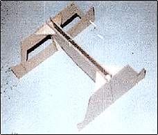
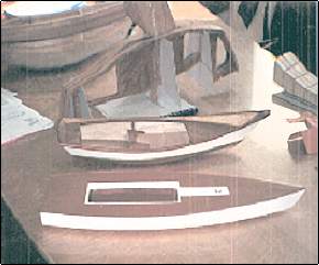
Plot the measurements on a plywood panel. Rip a 1"x2" at flare angle, glue
these inwale slats along the plotted points. Cut off the outside excess at
flare angle. See the photograph. A Japanese pull saw is ideal for this
exercise.
Placed on three sawhorses, the deck panel provides a perfect platform for
the rest of the hull construction without the need of a building jig.
Attach the carlings. Cut out the cockpit space as shown in the picture.
The cross strips are easily removed after the hull is finished.
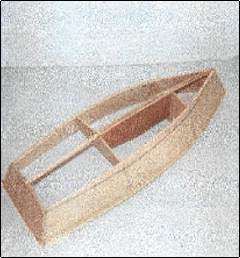
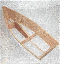
Place the bulkheads fore of station line #4 and aft of station line #11 on
the platform. They are held plumb by a longitudinal bow frame fore of
station line #4 and a longitudinal transom frame aft of station #11. Next
is the (bottom) half frame at Beam.
My experience is that making notches in the inwales without cutting into
the deck and gluing the cross frames in these notches works a lot easier
and actually makes the setup stronger than notching the frames over the
inwales.
The 1"x1" linings on each side of the longitudinal frames take care of the
king planks and the keelson. The cross frames are lined all around in the
same way with 1²x1² slats. The model frame in the photographs is mounted
on a 1"x2". |
| Sometimes, I hang the side panels first before the chines are placed.
The easiest way to attach the chines is on the outside, but IMO that makes
an ugly sight. |
Fig. 4 2 Three chine
solutions
This can be (partly) overcome by the compromise shown in the middle
drawing: a 1"x2" is ripped at flare angle and attached as shown.
Personally, I prefer the chines on the inside.
After the hull is turned over, if you leave the sides as they are, you end
up with a very stiff, comfortable skiff. If you cut the side panels flush
with the deck you obtain a flat, Laser-type wet-sailer that will stand up
to rough treatment, and that is easy to car-top even if it is made from
low-cost, lightweight, 1/8" Lauan. |
| Make sure to seal the insides of the bow and transom (air) chambers
before placing the bottom. Plastic resin glue works well for this purpose.
IN THIS BUILDING METHOD THE HALF-BREADTH DRAWING OF THE
DECK
IS THE PRINCIPAL GUIDELINE!
You cant go wrong with this method. All the correct bevel angles of
the cross frames are directly taken from the deck contour line.
The strongback-sandwich method
Howard I. Chapelle briefly mentions this method in his Old Testament of
the boat-builders' Bible "BOATBUILDING" (1941) on page 199, and
illustration #52.
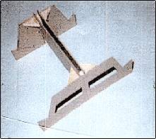
A frame is made in the exact shape of the Profile view projection drawing.
THE PROFILE DRAWING IS THE MAIN GUIDE
FOR THE CONSTRUCTION OF THE PROJECT!
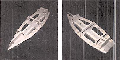
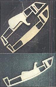 The
photograph at left shows such a frame for the San-Francisco Pelican. Two
panels of 1/8" Lauan separated by 1"x2" stock and lined on the outsides by
1"x1" works fast and easy. Remove the excess plywood after the frame is
put together. It makes a lightweight, strong "spine" that stands on its
own even before the cross frames are attached. The
photograph at left shows such a frame for the San-Francisco Pelican. Two
panels of 1/8" Lauan separated by 1"x2" stock and lined on the outsides by
1"x1" works fast and easy. Remove the excess plywood after the frame is
put together. It makes a lightweight, strong "spine" that stands on its
own even before the cross frames are attached.
It is not necessary to build all the full-sized hulls to obtain the
insight and the experience. A to (1/6) scale model made from 2-mm
cardboard will do. Actually, making a model of this low-cost material is
slightly more difficult than the real "McCoy" because of the smaller
tolerances and the cheap quality of the material.
|
The "third" alternate method
I call it by that name because I can't think of a better name.
If you have tried all the methods mentioned before, you are no longer a
beginning amateur but you have become familiar with the measurements. You
have gained a lot of insight in the lines and the proportions of a hull.
In this method, you assemble a centerboard box and attach the bulkhead at
station #4 and the cross frame at station #8. This is the building jig.
Cut the side panels. Attach the panels to the bow stem. Place the panels
on the setup. Line up station line #4 and #8 (Beam) of the panels on the
bulkhead (#4) and the (half) cross frame (#8). Hold the side in position
with clamps. Bring the panels aft together with a Spanish windlass to
attach the transom.
It is the simplest method as long as you know what you are doing, |
The beauty of trying all these methods is that you can do it on the
kitchen table during the (too) long North American winter season. It shows
you exactly how to prepare the parts of your hull in kit form. It will
give you a head start on the (too short) summertime.
Sheers and Chines, Barend. |
Back
to Part 3
On to Part 5

|