|
Often I hear the comment: “Look, it was a long time ago that they tried to
teach me mathematics in secondary school.
I never could get excited about it.
I have never needed it later in my life.
Now it looks and sounds like gobblegook to me.
Can’t you do it without any calculations?”
And it may surprise you that the answer is:
“Yes, you can if you know what you are doing, and have an eye
for the obvious.”
Let me give you an example:
In Algebra, a letter replaces often a very large number.
The purpose of using letters is to replace these big numbers by a
few letters and/or symbols and reduce the problem to something that
(relatively) anybody can understand.
Here is a little brainteaser:
The letters O, T, T, F, F, S, S, … represent a simple series.
What is the next letter of the series?
If it keeps you awake one week after you read this and
still don’t know the answer, you can reach me at 514-631-6431.
But don’t feel bad. I
overlooked the OBVIOUS myself.
Even if you don’t have your own house on a big lot, you
still know that an area is determined by its length times its
width, or Area = l x w.
You learned that in elementary school. For a lot of us, it is the only practical application of
mathematics that we ever needed.
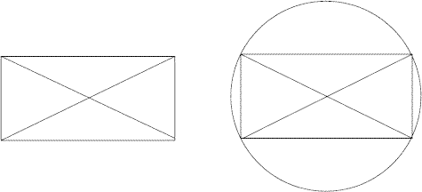
If a diagonal is drawn in the area rectangle, the area of
the two right triangles is a half times length times width, or Right
triangle area = ½ x l x w

Fig. 5 - 1
The diagonal is the
hypotenuse of a right triangle.
The long leg is the length of the rectangle.
The short leg is the width.
In figure 4-2, the second diagonal crosses the first
on exactly at its middle point.
Obvious, a circle with a radius equal to half the length of a
diagonal passes through all the four corners.
The diagonals are two middle lines of the circle.
That applies to ANY drawing made that way:
Any two lines drawn from the opposite ends of a
middle line of a circle to the same point on the circle line make a right
(90º) angle with each other!

Fig. 5 - 2
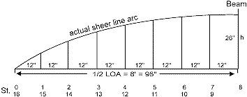
In the next drawing fig 4-3, the chord is half the
actual Overall Length of a double-ender.
The circle arc represents half the actual
sheer line arc. The Overall
length is 16 foot, or LOA = 16'.
The constant flare ratio of Profile height to Beam is:
Profile Height/Beam =10/24.
In a double-ender, the half fore of Beam is exactly the same
as the half aft of Beam.
Only one half of the sheer line circle arc segment needs to be
drawn to get the full picture.
Note the station numbers under the drawing.

Fig. 5 - 3
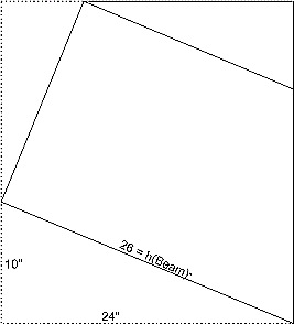
The actual sheer line in figure 4-4 is exactly the same as
In figure 4-3. On the
vertical line h, which is the maximum height of the circle arc, half a
circle is drawn. Any two
lines drawn from both ends of this middle line h make a right (90º) angle
with each other.

Fig. 5 - 4
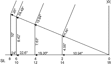
Figure 4-5 is a simplified half Body view of the double
ender. At Beam, the
half-Breadth is 24"; the Profile height is 10".
The sheer line/hypotenuse is the same line h as in
figure 4-4. The long leg of
the right triangle is the half-Breadth at Beam, 24".
The short leg of the triangle is the Profile height at Beam,
10".

Fig. 5 - 5
If this is true for Station
#8 (Beam) it is true for all stations
The OBVIOUS conclusion is that on the hypotenuse of
the 10"-24"-26" right triangle the heights, h(n) of all the station
lines can be set off.
Don’t measure, use a compass, it is much more accurate.
In the right triangle all the measurement of the offset table are
shown to two decimal figures accurate.
To keep the drawing clear, only the even stations are shown.
This triangle contains ALL the Profile height and half-Breadth
measurements of the sheer line.
Actually, to make the cross frames, it is no longer necessary to
make a time consuming half-Breadth view drawing, and/or a Profile view of
the sheer line. These
drawings have become redundant.
You probably will agree with me that this simple drawing is easier
to read, with less chance of making mistakes than a conventional offset
table with its plus (+) and minus (-) signs that make these tables look
like ancient hieroglyphs found on tablets from archeological digs in the
Middle East.
If the full-sized illustration is made
accurately, just take off the measurements with a compass to construct the
cross frames. There is even
no need to put the measurements figures in as is done in this
illustration.

Fig. 5 - 6
Cross Frames
Besides the measurements for the cross frames, you
have to know their exact bevel angles.
That is one of the easiest hurdles to overcome.
The bevel angle of the frames at each station is equal to the
center point angle between the radius of the actual sheer line circle arc
at station #8 (Beam) and the radius to that particular station. Angles come pretty accurate, even in a much smaller to scale
drawing. Personally, I always
check them with a protractor.
But when it comes to a table saw setting, I make a right-angled template
first from any inexpensive stiff material.
How this is done is shown in detail in figure 2-5 in the second
article in this series.
Side Panels Fore and Aft
Constant flare angle are easy to cut on a table saw.
To obtain constant flare angles for the stem and the sides of the
transom, the side panels are allowed to go straight fore and aft. It is
clearly shown in the photograph of the Lunenburg dory on page 8 of the
preceding article (#III) in this series. The side panels continue as the tangent line to the circle
arc segment of the sheer line.
And by definition, a tangent line makes a right (90º) angle with
the radius at that point of the circle circumference.
When the drawing is made accurately to scale it shows exactly where
this tangent line crosses the center line if you need that point for
adjustment of the LOA of the hull fore at the bow.
Check figure 3-2 in the preceding article in this series.
Bow and Transom Rake and Length
Every rule has its exception! Earlier, I mentioned that being able the show the offset
table in the form of a simple right triangle drawing as in figure 4–6 make
the half-Breadth and Profile drawings redundant.
I still need only two small parts of the Profile drawing to show
the rake and the exact length of the bow stem, and the transom board.
But again, this needs only to be drawn as figure 3-5 illustrates.
Last “SNAG”
Perhaps you notice that except for the formula
AREA = L x W at the beginning of this article not a single other
formula is used.
This should come as a relief for all the aspiring amateur boat builders
who keep procrastinating to start because of their unfamiliarity with, or
adversity to any mathematical subject.
The only reason why you can excuse yourself further
is that to be able to start with the drawing, you have to calculate the
length of the radius R of the circle segment arc of the actual circle.
Look at the two worked out tables at the end of the
third article in this series.
The last column of the first table on page 9 gives you the answer for
any type of flare angle you choose for any type of hard-chined
boat that can be developed from a 16-foot double-ender.
Once you have made your choice, the figures in the second table
provide you with an opportunity to double check the heights of the circle
arc segment at each station against your own findings.
Easy Full-Sized Lofting
Fig. 5 - 7
I have a 20-foot measuring tape.
At exactly one inch (1"), I drilled a small 1/8" dia. hole.
I drill, for example, a second hole
in the tape at 191.25".
Both holes are not in the middle of the width of the metal tape but
only 1/8" from the edge of the strip.
By putting a sharp nail in the first hole and a sharp pencil
point in the second hole, I can draw accurately a circle with a 190.25"
radius, or any other radius for that matter by drilling an additional hole
to place the pencil.
I take an inexpensive 4'x8' panel
of Philippine mahogany. On it, I draw the seven station lines from #1 to #7
inclusive, 12" apart.
The edges of the panel represent the station lines #0 and #8 (Beam).
On this last edge, I mark off 26".
On a straight line on the floor, I line up the tape with the
station #8 edge of the panel.
Temporarily, I place the nail in the hole at 191.25" right beside
this mark. On the straight
line, I mark the center point of my circle arc segment.
I move the nail to this center point and draw the (half) circle arc
segment on the plywood. If it
is done correctly, the line ends at the bottom corner of the other edge,
station #0 (= station #16).
When I am satisfied with the
accuracy of the actual sheer line arc on the plywood, I draw the radius at
each station on the arc but only for a few inches to be able to measure
the angle between the station line and the radius for the correct bevel
angle setting of the cross frame.
Sheers and Chines (forever), Barend. |