|
Part 2: Modeling
The first installment of this series detailed my search for a boat design in the 18-foot range that would be suitable for fishing, photography and swimming on large Maine lakes. My wife and I wanted a boat with a cabin big enough for a porta-potty that would also be conservative of resources, easy to look at, and reasonably easy to build. After narrowing the field down to four final candidates, I decided to base my design on the Chesapeake Bay crabbing skiff, a type I’d built before and whose seakeeping characteristics I was fond of.
Now I want to backtrack a little and explain the process I followed to decide between the last two finalists--the crabbing skiff and a modified Hartley Trailer Sailer. A traditionalist would probably carve half models at this stage of the game. But since I wanted to find out not only what the finished boat would look like in three dimensions, but also what construction problems to anticipate (and because I can’t carve worth a damn), I decided to build my models as near as possible to the way the real boats would be built: according to the plans.
The Hartley model came first, because at this point I really thought I’d be going in that direction. The chosen scale was an inch and a half to a foot, since I’d used this scale before and liked it: The pieces were usually big enough for my clumsy fingers to manipulate, and the measuring was convenient, since an eighth of an inch on the model equals a full inch on the real boat.
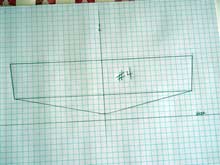
Hartley plans are a little different from some, in that there’s no table of offsets to loft from. Instead, the parts deemed critical by the designer (the frames and the stem pieces) are represented by full-size patterns that you can trace right onto your stock. Nice for a builder, to be sure, but not much use for a model-maker. Luckily, the plan I was using (the TS 16) also has smaller-scale drawings of those parts that I was able to scan--you have to be a creative plan-folder to get everything into the scanner--and print out. Here’s one of those smaller drawings:
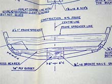 |
photo 1: plan view
click images for larger views |
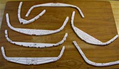
After a bit of playing with the magnification on the copier, I was able to produce properly scaled drawings for my model. These I pasted onto scraps of thin plywood paneling and cut out on the band saw. The resulting scale-model frames and stem are shown below:
| photo 2: frames cut out |
 |
The Hartley boats are built on a strongback, for which detailed dimensions are provided in the plans. I built a little one out of scrap wood. Since I wanted to stretch the 16-foot boat to 18 feet, both to get the desired length and to reduce the overall beaminess of the design, I increased the length of the scale strongback and the spacing between frame positions accordingly. The new dimensions were drawn on a piece of heavy art paper which was then folded over the strongback and attached. Alternatively (with smoother lumber than the scrap I was using) you could just mark the dimensions directly onto the wood. The photo below shows the strongback with frame positions marked and blocks for frame attachment secured. You’ll also see a little pile of frames, to which the temporary crosspieces used to position the frames on the strongback have been attached.
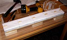 |
photo 3: strongback with markings |
The next photo shows the frames on the strongback. On the right you can also just barely see the stem, installed on an extension whose dimensions are given on the plans. Frames were installed with half-inch, 19-gauge nails through pre-drilled holes in the cross pieces, not glued. This part is a real test for the fumble-fingered; I had more success pushing the nails into place with needle-nose pliers than with hammering., which tends to knock the blocks loose from the strongback. A notched backer stick big enough to get a good grip on (not shown) kept me from knocking the whole model on the floor while I was forcing the nails in.
| photo 4: frames and stem installed |
 |
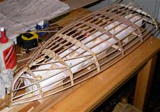
The stem is more visible in the next photo. The model actually started to look like a hull when the longitudinals were attached. These weren’t exactly proportional in cross section to the full-size ones on the plans, but they were the closest sizes available in basswood at the hobby store. You’ll also notice a lot of pins stolen from my wife’s sewing room.holding the pieces in place while they dried. Krazy Glue probably would have been a better choice than the Titebond due to its instant adhesion, but since I was out of Krazy Glue and didn’t feel like making a yet ANOTHER trip to the hobby store, I used what I had. Ignore the beer can..
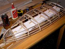 |
photo 5: longitudinals |
Here’s the completely framed hull. Kind of pretty, I think.
| photo 6: hull fully framed |
 |
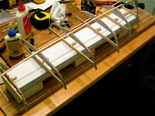
Now the planking went on. Here I used balsa instead of basswood for its greater flexibility. This photo didn’t turn out very well, but you can see the great lengths I had to go to to hold the planking in place while the glue dried.
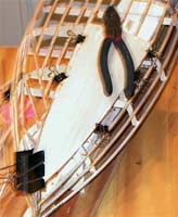 |
photo 7: planking |
You’ll have to take my word for it that I finished the planking. I did, but then shortly thereafter we moved, and the Hartley model was a casualty when something fell on it in the back of the truck. I suppose I could have repaired the damage and finished it, but the model had aleady served its purpose: I now knew something about the construction sequence and which parts of it were likely to be problematic. I also knew that the multiple-frame design with lots of small-dimension longitudinals was a fussier building method than I probably wanted to deal with on the full-size boat. Some time went by as accommodating ourselves to the new house took precedence over boat design. By the time I was able to get started again on the boat project, I’d already had the unpleasant experience with the Hartley plans folks that I detailed in the first installment of this series. Time to look at my other “finalist”: a Chesapeake Bay crabbing skiff .
Crabbing skiffs need only one mold. The sides are fastened at the stem, sprung around the mold, and then attached to the transom (or to another stem on the ones with two pointy ends). The best explanation of this process is in Sam Rabl’s Boatbuilding in Your Own Backyard; Reuel Parker’s The Sharpie Book also covers it. The boat takes its shape from the sides bent in this way, much as you’d draw a fair curve using a batten. It’s a satisfyingly simple way to get pretty hull lines. But even though I’d already built one of these boats and was thoroughly familiar with the traditional way of putting one together, there were still some obstacles to overcome for the current project: I wanted a lighter, more easily driven boat than the massive oak and yellow pine ones I was familiar with. I also wanted to find a simpler way to plank the hull than the staved-bow, herringbone-planked old-fashioned way, so that I could go from project to boat in a reasonable time. Time to play around with some more models.
Since I was working from plans--this first model was based on the Applegarth sailing skiff on p. 54 of the Cheaspeake Bay Maritime Museum’s A Heritage in Wood--with no “developed” shapes for the sides, I decided that I could get a rough three-dimensional idea of the hull lines by lofting a scale model mold, stem and transom from the plans, then bending the gunwales and chines around these forms. For the mold shape I used the station measurements at the widest part of the hull, lofted onto graph paper in the same inch-and-a-half-to-the-foot scale as the Hartley model. The developed transom was drawn the same way.
| photo 8: mold drawing |
 |
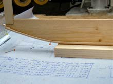
To form the backbone of the model, I lofted the rabbet and chine lines onto a piece of scrap paneling which was fastened to a scrapwood base. I cut notches in the paneling to accommodate the stem and mold; the transom angle was cut into the stern end. In cutting out this backbone I made a pretty serious mistake. To avoid planking difficulties (read “staving”), I decided to eschew the deep traditional forefoot on the plans in favor of a keel that curved up to meet the chines at the bow in the manner of the “modified sharpie” at the top of p. 13 in Ted Brewer’s Understanding Boat Design. The mistake was that I drew the new keel line with a French curve rather than a batten. It looked OK as a pencil line, but when I attached a piece of balsa to it to give me a ledge to attach planking to, I could easily see that it wasn’t at all fair. The first photo below shows the stem, mold and transom attached to the backbone; the second shows the unfair line.
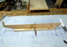 |
photo 9: completed backbone. |
| photo 10: unfair line |
 |
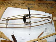
Since I had come this far, I decided to go ahead and spring the gunwales and chines into place, just to see what I had. The next photo shows the result. Although lots of the details of a “real” model are missing, the quickie model does give a good feel for what the overall shape of the boat would be. I named it a “ghost model,” after the beautiful “ghost frames” erected on the foundations of colonial buildings at historic St, Mary’s City, Maryland, where our daughter went to college.
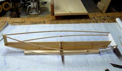 |
photo 11: gunwales and chines |
Another thing I noticed about the ghost model was that it was really quite rigid once the glue dried. Which got me wonderng if I hadn’t accidentally discovered my new, lighter way to build a crabbing skiff. Could the gunwales and chines not only determine the shape of the boat, but also provide most of its structural strength? That’s how skin-on-frame kayaks do it--why not a skiff? How about a structure made of heavy-duty gunwales and chines, covered with a thin plywood skin? No doubt somebody else had though of this before, but I hadn’t ever seen it. I made a second ghost model, this one in a smaller scale (one inch to a foot) based on Lark, another design from A Heritage in Wood. I also tried putting this one together stitch-and-glue fashion using strands of copper ground wire through pre-drilled holes. The Lark ghost model had its own keel rather than the massive backbone--photo below shows the keel being glued on--to see if it really was as rigid as I’d thought it would be. It was. I determined to translate the lessons of the models into a real boat.
| photo 12: Lark model |
 |
On to Part 3 - Back to Part 1 |