|
Obsolete Outboards |

|
| by
Max Wawrzyniak - St Louis, Missouri - USA
Bringing
a 1956 Johnson 15 hp Back to Life
Part
III: Removing
the Flywheel and Magneto |
 |
Part
1 - Part
2 - Part 4 - Part
5 - Part 6 - Part
7
Before we get started on the magneto, you
might want to review the magnetos
column.
Some people like to check for "spark" before
they start mess'n with the magneto. Checking for spark
means removing the sparkplugs from the cylinder head,
gounding the outer metal casing of the sparkplug to
a good "ground" (bare metal) somewhere on
the engine, and with the spark plug wires still attached
to the plugs, cranking the engine with the recoil
starter or with a piece of rope wrapped around the
flywheel. If everything is working correctly you should
be able to see the plugs sparking and also hear an
audible snapping sound. A white spark or blue spark
is preferable to a yellow spark.
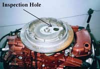 |
SF17 -
"Inspection" hole in flywheel
through which you can check for cracked
coils. You can also adjust the ignition
points "gap" (we will get to
that) through this hole.
(click
images to enlarge) |
|
I don't bother with checking for spark before tearing
into the magneto. If I intend to run the engine myself
(and I rarely work on other's engines) then I want
it to have a tune-up. The cost of putting new ignition
points and condensers, new spark plugs, and maybe
new spark plug wires into one of these old OMC outboards
is usually no more than about $25.00 assuming you
buy the parts and install them yourself. When you
pay a shop to work on your outboard you will usually
end up paying full retail price for the parts, but
with a bit of shopping you can often buy the parts
(to be isntalled by yourself) at a discount, which
means you not only save the labor charges but also
save a little on the cost of the parts themselves.
Replacing these items, which are more-or-less considered
"expendables" or "consumables"
will save you some frustration when it comes to getting
the engine into running condition and will also give
you a better-running engine.
As mentioned in the Magnetos
column, the one area of weakness in all
1 and 2 cylinder OMC engines manufactured from about
1951 until the late 1960's are the magneto coils.
These coils, which resemble round plastic cylinders,
always go bad, without exception. If your engine has
the original coils, it is a sure sign that the engine
has seen very little running (if any) in recent decades,
and the coils will have to be replaced. Many OMC outboards
you will run across, however, will have already had
the coils replaced and as the replacements rarely
go bad you can run them.
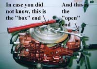
| SF18 - A box-end
wrench provides a much better grip on the
flywheel nut than an open-end wrench does.
Less chance of "stripping" the
"flats" off the nut, especially
if you hit the wrench with the hammer as
I do (not recommended by the factory) |
|
|
With the recoil (pull rope) starter removed, look
to see if there is an inspection port (hole) in the
top of the flywheel; most all of the old OMC outboards
of under 25 hp had this hole. Usually it had a sheet
metal cover although often the hole cover is missing.
Have a look down into this hole as you slowly rotate
the flywheel by hand (OSHA would have you remove the
spark plug wires to be sure the engine does not start
while you are turning the flywheel. Yea, right. Removing
the spark plugs as well makes the engine easier to
turn - no compression). You will see the two cylindrical
plastic coils which may be green or red or purple
or maybe some other color. If there are cracks evident
in the plastic, you have bad coils even though you
just might still get a spark out of them. No cracks,
and the coils are PROBABLY good. Replacement coils
can be had at Johnson and Evinrude dealers or aftermarket
Sierra coils (part # 18-5181) can be purchased through
any boat dealership or through NAPA auto parts. The
Sierra coils list for about $21 each and sometimes
the boat dealers will discount them a little. By the
way, only turn that flywheel clockwise, looking down
on it. Otherwise you risk damaging the water pump
impeller you just installed.
In order to go any further, one (you) must remove
the flywheel. The proper way to lossen the flywheel
nut is to hold the flywheel stationary with a big
strap wrench while loosening the nut with another
wrench. I don't have a strap wrench big enough to
go around the flywheel so I put a box-end wrench (better
than an open end wrench, and a six-point box is better
than a 12 point box; if you don't know what I am talking
about, do a Google search) and give it a persuasive
tap with a hammer while holding the flywheel still
with the other hand which also holds the wrench from
sailing.
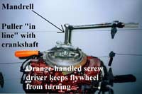 SF19
- The puller in place on the flywheel: note
that the puller mandrell (center big screw)
is in line with the engine's crankshaft,
that the (3) smaller bolts are threaded
fully (but not excessively) into the (3)
holes in the flywheel; that the flywheel
nut has been "backed-off" a few
turns but is still on the crankshaft and
lending support to the crankshaft (but the
nut is NOT taking the thrust from the puller
directly). The orange handled handled screwdriver
is to keep the flywheel from turning as
the mandrell is tightened. SF19
- The puller in place on the flywheel: note
that the puller mandrell (center big screw)
is in line with the engine's crankshaft,
that the (3) smaller bolts are threaded
fully (but not excessively) into the (3)
holes in the flywheel; that the flywheel
nut has been "backed-off" a few
turns but is still on the crankshaft and
lending support to the crankshaft (but the
nut is NOT taking the thrust from the puller
directly). The orange handled handled screwdriver
is to keep the flywheel from turning as
the mandrell is tightened. |
|
Loosen the nut a few turns but don't remove it: leave
it threaded onto the crankshaft (which is what the
flywheel is bolted to) and set-up your flywheel puller.
If you don't have a flywheel puller you are going
to need to borrow one or buy one. While I don't intend
to endorse any one tool source over another, something
like this will work just fine.
You might need to stop off at the hardware store
if the bolts for the "legs" that come with
the puller are the wrong diameter to thread into the
three holes in the top of the flywheel. You do NOT
want to use a puller that lifts up on the other rim
of the flywheel as that may damage the flywheel. the
puller MUST pull from the three threaded holes on
the top of the flywheel.
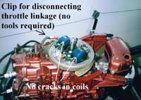 SF20
- The flywheel has been removed, revealing
the magneto. The coils do not appear to
be cracked and we will assume that they
are "good." If you are only replacing
the ignition points and condensers there
is not need to remove the magneto from the
engine. I would strongly suggest, hwoever,
replacing the spark plug wires with new
metallic core (not graphite) wires if the
old ones appear to be stiff and brittle
or are cracked, in which case you will need
to remove the magneto from the engine. Note
the little sheet metal clip that can be
used to disconnect the htrottle linkage
that rotates the magneto for "spark"
advance. SF20
- The flywheel has been removed, revealing
the magneto. The coils do not appear to
be cracked and we will assume that they
are "good." If you are only replacing
the ignition points and condensers there
is not need to remove the magneto from the
engine. I would strongly suggest, hwoever,
replacing the spark plug wires with new
metallic core (not graphite) wires if the
old ones appear to be stiff and brittle
or are cracked, in which case you will need
to remove the magneto from the engine. Note
the little sheet metal clip that can be
used to disconnect the htrottle linkage
that rotates the magneto for "spark"
advance. |
|
Thread the three bolts down through the puller and
into the three holes of the flywheel as shown in above.
The bolts must be fully-threaded into the holes, but
if the bolts are threaded so far into the flywheel
that they protrude underneath, and if the flywheel
is then rotated, the bolts can damage the ignition
components under the flywheel. Once the puller is
installed, do not allow the flywheel to turn. The
puller is tensioned by turning the large threaded
center mandrell (bolt), the bottom of which has a
pointed do-dad on it which will self-center in the
center depression machined into the end of the crankshaft.
The flywheel nut should remain on the crankshaft threads
to help support the crankshaft but the puller should
bear against the crankshaft and not the nut. Be sure
that the nut is loosened a few turns, however.
I use a large screwdriver inserted into the legs
of the puller to keep the flywheel from turning as
I tighten the mandrell, but the proper tool to use
is that big strap wrench which I don't have.
 SF21 - The (4) screws marked #17 are the
screws that secure the magneto to the engine.
The item marked #15 is the clip for disconnecting
the throttle linkage so that the magneto
can be removed. Although this linkage may
be different on some larger engines, the
arangement of the rest of the magneto components
is common to all 2-cylinder OMC outboards
manufactured from about 1951 until the early
1970's.
SF21 - The (4) screws marked #17 are the
screws that secure the magneto to the engine.
The item marked #15 is the clip for disconnecting
the throttle linkage so that the magneto
can be removed. Although this linkage may
be different on some larger engines, the
arangement of the rest of the magneto components
is common to all 2-cylinder OMC outboards
manufactured from about 1951 until the early
1970's. |
|
Make sure that the mandrell of the puller is in-line
with the crankshaft and not leaning one way or the
other.
The flywheel is seated on a taper machined into the
end of the crankshaft and if the flywheel has not
been off in a long time, it may take considerable
tension to break the flywheel loose from the crankshaft.
How much tension is difficult to quantitfy. In other
words, I don't know. What I do is to screw-down the
mandrell of the puller as much as I dare. If the flywheel
has not come loose yet, I will lift up on the flywheel
and give the top of the mandrell a persuasive tap
with a hammer. If you grab the flywheel and lift up
on it, you will notice a tiny bit of "end play":
the flywheel and crankshaft will move up and down
a very tiny amount, maybe a couple of thousanths of
an inch. Have someone lift on the flywheel so that
the flywheel is at the upper end of it's end play,
and hit the top of the puller mandrell with a hammer-blow
straight down. Often this will break the flywheel
loose. Do NOT hit the puller with the hammer unless
the flywheel is being lifted, and make sure the hit
is square and straight. I don't know how to tell you
how hard of a hammer blow I give the puller, but it
is certainly not a "timid tap" nor is it
"everything I've got." If a couple of hammer
blows don't free the flywheel, put the hammer aside
and give the mandrell maybe another 1/2 turn or so
and then try the hammer again.
| SF22 - This
is the entire ignition system for (1) cylinder,
along with some of the potential problems.
The components are few and cheap: Why waste
your time cleaning and "dressing"
pitted points and checking for shorted condensers
when new ones for the engine will cost under
20 bucks? |
|
|
If a few hammer blows have not freed the flywheel
and you dare not put any more tension on the puller,
soak the crankshaft with penetrating oil (WD-40 is
not prenetrating oil) and let it sit over night.
If it still will not come loose, use a propane touch
(like is used for soldering copper pipes) and rapidly
heat the flywheel around the crankshaft while trying
to avoid heating the crankshaft too much, all the
time keeping the puller under tension. After heating
the flywheel for several minutes, put the tourch down
and try the hammer again.
Some combination of all of the above should free
the flywheel. If the flywheel hase been recently removed,
it may come loose easily with no need for hammers
or tourches or oil, but if it has been stuck on that
crankshaft for 40 or 50 years. you may need to use
all of the above in order to get it loose. By the
way, a really stuck flywheel will make one heck of
a "bang" when it pops loose.
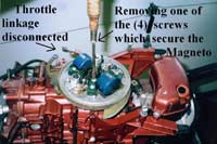 |
SF23 -
Removing the magneto: loosening the (4)
screws marked # 17 in Figure SF 21. Note
that the throttle linkage has been disconnected. |
|
Once the flywheel is removed you are looking at your
magneto (Figure SF 20). Each of the two cylinders
has it's own coil, ignition ("breaker")
points, condenser, spark plug wire and spark plug.
Other than some magnets embeded in the rim of the
flywheel, and a cam (eccentric) on the crankshaft
that acts upon the points, that is all there is to
the magneto and the whole ignition system (figure
SF 22). I highly recommend that you replace the ignition
points and the condensers at a minimum and these items
can be changed-out with the magneto remaining on the
engine.
If the spark plug wires look old and have turned
hard and/or have cracked, it would not be a bad idea
to replace those as well, and for that the magneto
needs to be removed from the engine (which is not
a big deal). The magneto also needs to come off if
you have cracked coils which need replaced.
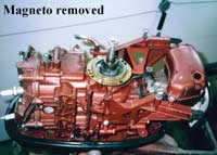
| SF24 - Magneto
removed. Unless the flywheel is really really
stuck on the crankshaft taper, you should
be able to go from a fully-assmebled engine
to this state of dissasembly in about 30
minutes or less. |
|
|
The magneto can be rotated back and forth and this
is how the igntion timing is advanced and retarded
as the engine is speeded-up and slowed down. The rotation
of the magneto is controled by an arm and bellcrank
arangement on the port side of the motor and there
is usally a sheet metal clip which can be removed
without tools in order to disconnect this linkage
(figure SF 20). Four screws (#17, Figure SF 21) are
loosened and then the magneto can be lifted up off
of the engine. Be carefull that the arms for the ignition
points do not "hang-up" on anything while
you are lifting the magneto off the engine. The only
wires hanging off the magneto will be the (2) spark
plugs wires, unless you have a "push to stop"
button in which case you will also have two small
wires. The small wires usually have disconnects which
are often hidden beneath little plastic sleeves on
the wires.
Since I keep reminding myself not to make any assumptions
about how much the reader knows, this is getting a
bit "wordy." and so the magneto work will
drag on into next month's column as well.
Bye Bye

click here for a
list of Columns by Max Wawrzyniak
|