|
Obsolete Outboards |

|
| by
Max Wawrzyniak - St Louis, Missouri - USA
Bringing
a 1956 Johnson 15 hp Back to Life
Part
IV: Magneto
Work |
 |
Part
1 - Part
2 - Part 3 - Part
5 - Part 6 - Part
7
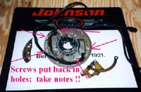
Have a good look at figure SF 25 (below). This is
your magneto. This is the thingy that makes the spark
plugs spark. In the very center is the crankshaft
(which you will not see on your magneto if you have
already removed the magneto from the engine. Instead,
you will see a hole where the crankshaft fits). Doo-dad
#4 is a cam (eccentric) which is a slip-fit on the
crankshaft. As the crankshaft rotates, the cam alternately
opens and closes the ignition points ("breaker"
points) which are #'s 10 and 20. You will see the
spring-loaded rocker arms which ride on the cam, and
which have the points at their outer ends. We are
going to install new points, but just as an "FYI,"
the most common problems with old points are that
their contact surfaces are dirty and/or pitted and
eroded. You can "clean-up" pitted points
with a special little points file or a bit of emory
cloth, and you can clean dirty points by allowing
the points to close on a bit of clean business card
and pulling the card out from between the closed points
several times. Other problems that occasionally show-up
are weak return springs and bent points rocker arms.
Have a look at figure SF 26 for some other protential
problems. Since most of these parts are pretty cheap
and you already have the engine apart, I suggest just
replacing the points and condensers. Why screw with
trouble-shooting old parts?
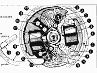 |
SF25 -
The magneto and it's parts
(click
images to enlarge) |
|
Numbers 2 and 13 on figure SF 25 are the condensers,
which have nothing to do with steam as their name
suggests. Some have commented that a more appropriate
term would be capacitor. Anyway, the condensers act
as short-term (very short-term, like a fraction of
a second) electrical current storage devices. Sort
of like a battery, but different. I won't go into
more detail because it will bore you and you don't
need to know more about condensers than I have already
written, and also because I really don't remember
much more about condensers and would have to look
it up. I do remember that condensers can fail in two
different ways. Notice that the condenser is a little
metal cylinder with a wire sticking out the end of
it. One way the condenser can fail is for there to
be short circuit between that wire and the metal case
of the condenser. This is easy to check for if one
has a multi-meter or even a little battery-powered
test light. There should be no electical connection
between the metal case and the wire; if there is,
the condenser is shorted and junk. The second way
a condenser can fail is that it can have an internal
problem that makes it weak or ineffective. One needs
a special testing device for detecting this problem.
But condensers for our favorate old OMC outboards
from 1955 to 1972 (are so) are dirt-cheap to buy so
why bother with testing old condensers at all? Just
replace them.
| SF26 - Yeah,
you've seen this before. You know, you can
replace most of this stuff pretty cheaply
and then you don't have to trouble-shoot
problems with it. |
|
|
Numbers 5 and 16 on SF 25 are the coils. As with
the points and condensers, there is one for each cylinder.
The coils are cylindrical plastic things mounted on
the middle "leg" of a three leg metal thing
constructed of many layers of metal riveted together.
The plastic coils and the laminated metal are considered
a single component in these old OMC engines, although
with other brands of engines one could replace the
plastic coil separately from the laminated metal thing.
The coils orignally installed in these old OMC engines
always went bad, without exeception. If the coils
on your engine have cracks in the plastic casing,
they are bad. No cracks, and probably your engine
has had replacement coils installed and most likely
they are good. Uncracked coils can go bad but it is
rare, and anyway the only way to test them is to use
a special testing device, which you don't have. You
can spend a lot of money buying one...
or if you are handy you can try building
your own coil tester... or you might be able to take
your coil to a local small engine/outboard motor repair
shop and have them test it for you. I just assume
that if the things are not cracked, they are good,
and I don't give them a second thought unless I have
already replaced the points, condensers, spark plug
wires and spark plugs and still do not get a spark.
| 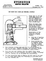 SF27
- How to install the spark plug boots
on the ends of the spark plug wires. Make
sure that the pointed end of the coiled
wire goes through the center of the spark
plug wire so as to make contact with the
wire core of the spark plug wire. Disregard
#5; you won't have a choice like the old
boys did 50 years ago. The "slip-one"
end is the only end available on Champion
J8C plugs (or equivalent) , which are
the plugs recommended for most 1950's
and 1960's OMC outboards of under 35 hp
or so. SF27
- How to install the spark plug boots
on the ends of the spark plug wires. Make
sure that the pointed end of the coiled
wire goes through the center of the spark
plug wire so as to make contact with the
wire core of the spark plug wire. Disregard
#5; you won't have a choice like the old
boys did 50 years ago. The "slip-one"
end is the only end available on Champion
J8C plugs (or equivalent) , which are
the plugs recommended for most 1950's
and 1960's OMC outboards of under 35 hp
or so.
|
|
What about them spark plug wires? Chances are they
are the orginal wires and that they are getting old
and stiff and cracking. Unless you are real sure that
the wires have been replaced at some point in the
recent past, I would go ahead and replace them. They
could have some small cracks that could cause short
circuits and could drive you nuts trying to track-down
the problem. I try to minimize frustrations in my
life, so I always replace the wires. You will need
some metallic-core spark plug wire, which you can
usually buy by the foot. I use Sierra-brand spark
plug wire, which I bought a while back
in a 100 foot reel - part # 18-5226. Sierra also sells
a package containing 25 feet of wire and a bunch of
useless (to you) fittings, part # 18-5225. Since you
will need a lot less wire (measure the lengths of
your old wires, allow a bit extra, and note that the
wires are of different lengths), try calling local
boat dealerships and small engine repair shops and
you will find people selling this stuff by the foot.
There are other brands, of course, but do not get
talked into buying graphite-core wire. Before you
close-out the PDF, note the spark plug boots, 18-5750.
I always re-use the old boots on new wires, unless
the old boots are torn.
The spark plug wires are removed from the coils
by simply pulling on the wires; there is a little
spike inside the hole in the coil on which the wire
is impaled. The rubber boots on the other end of the
wires can also just be pulled off but try not to tear
the rubber. Note the little wire scroll inside the
boot; it is a seperate piece and not molded as part
of the boot. Figure SF27 shows how to install the
boots on the new wires. Note that #4 recommends the
use of a special silicone lubricant to make installing
the boot easier; it is really really hard to get one
of these boots on without some kind of lubricant.
I usually use an ordinary silicone spray lubricant
, but have on occasion used a drop of 2-cycle motor
oil. Don't use too much lubricant. Also, disregard
# 5 on SF 27; times have changed and one no longer
has a choice of terminals on one's spark plugs. By
the way, the spark plugs to use on this 1956 15 hp.
and on virtually all 1950's and 1960's OMC's are Champion
J8C or equivalent.
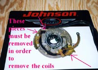
| SF28 - You
have to remove stuff from the underside
of the magneto in order to remove the spark
plug wires. The plug wire for the top cyclinder
is usually marked with a little metal band;
keep track of which wire is which. |
|
|
If you are installing new coils or if you are temporaily
removing the old coils in order to install new sparkplug
wires on them you will need to remove some of the
hardware from the bottom of the magneto ("stator")
plate. I really suggest taking careful notes and even
photos as these stator plates often are used on several
different models of engines and so often have extra
holes which may make reinstalling the bits and pieces
more complicated than you think. I find it helpful
to put the screws back into their holes as soon as
a part is removed, rather than tossing all the screws
into a coffee can and then later trying to figure
out which screw went where.
Once the "gingerbread" is off the bottom
of the magneto/stator, you can flip it right side
up and loosen screws #3, 8, & 18, figure SF21,
plus one screw on that diagram which excaped being
numbered. Note that in additon to the fat sparkplug
wire on the bottom, each coil also has a small wire
attached under one of it's mounting screws (a ground
wire) and another small wire that attaches to the
ignition points under a screw which also holds the
wire from the condenser. Unfasten these small wires
and lift the coils off the plate. If you are reusing
the old coils, pull the spark plug wires out of them
and push your new spark plug wires (cut to the appropriate
length) into the hole and secly onto the little spike
inside the hole. Note that there should be a little
rubber boot covering the joint where the spark plug
wire connects to the coil- be sure to re-install the
little boots.
Here's something important: make sure you know which
spark plug wire goes to which cylinder. usually there
is a little metal tag on the "top" spark
plug wire- be sure to transfer it to the new wire.
What happens if you lose track of which is which?
Figure SF25 provides some helpfull hints. Also, if
you try to start an outboard with the spark plug wires
reversed (and everything else is correct) it will
back-fire and yank the starter cord violently out
of your fingers.
 |
SF29 -
Stuff removed from underside of magneto.
I always put the screws back into their
holes. Makes keep track of which screw
goes where a lot easier, and lessens the
chance of losing a screw.
|
|
When re-installing the coils to the magneto (stator)
plate, one has to set the "air gap": No
big deal at all, actually; the "air gap' is the
distance between the laminated metal "heels"
of the coils and the inner circumference of the flywheel.
The flywheel contains magnets, and the goal is to
have the coil heels as close to the magnets as possible
with out actually rubbing on the spinning flywheel.
To set the air gap, one merely loosens the coil mounting
screws and moves the coil around until the outer surface
of the heels is flush with a machined surface on the
stator plate directly below the heels. Figure SF30
shows the heels and the surface directly below the
heels; just rub your finger across the joint between
the heels and the machined surface and if you feel
no "step" as your finger crosses the joint,
tighten the coil mounting screws and re-check to make
sure the coil has not moved. Once the coils are mounted
you can put the "gingerbread" items back
on the bottom of the magneto.
With the magneto right-side up, the condensers can
be removed. Have a good look at figure SF30 and SF31:
remove the screw from the points which holds the wires
from the coil and condenser (and the wire from the
kill switch, if your engine has a kill switch). Then
remove the single screw which secures each condenser.
 SF30
- Setting the coil "air gap" just
means making sure that the outer ends of
the coil heels are flush with the machined
surface directly below them. The holes in
the coils for their mounting screws are
slightly over-sized so that the coils can
be moved around slightly to make this alignment. SF30
- Setting the coil "air gap" just
means making sure that the outer ends of
the coil heels are flush with the machined
surface directly below them. The holes in
the coils for their mounting screws are
slightly over-sized so that the coils can
be moved around slightly to make this alignment. |
|
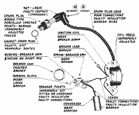
Now to the ignition points, AKA "breaker points"
or just "points." The points are actually
in two pieces: a "base plate" and a "rocker
arm." The actual contact surfaces of the points
are two tiny round metal disks, one of which is mounted
on the stationary base plate while the other is mounted
on the rocker arm, which pivots on a little axle or
shaft. The points are spring-loaded to be in the "closed"
closed position (contacts together) and the cam rotating
on the crankshaft moves the opposite end of the rocker
arm to "open" the points. Although you can
buy points and condesners seperately, I would suggest
that you buy a tune-up kit, which includes (2) points
rocker arms, (2) points base plates and (2) condensers.
You need one kit per engine, and you can either get
the official OEM kit from a Johnson or Evinrude dealer,
or you can buy a Sierra brand kit from virtually any
boat dealership (regardless of what engine brand they
carry0 and also from NAPA auto parts stores. The Sierra
kit I used on the 1956 15 hp was part # 18-5006, which
also fits the 5.5 hp, 7.5 hp, and 10 hp models of
the 1950s and early 1960's, and also 18 hp up to about
1961, and a few other models as well. List price for
the kit is about $20.00
Remove the tiny wire clip which holds the rocker
arm onto the littlte shaft that it "rocks"
on (needle nose pliers work well here). Notice also
that there is a flat sheet metal clip (usually copper
colored) which secures the spring that holds the rocker
arm in the "points closed" postion; this
clip needs the be removed as well and then the rocker
arm can be lifted off. The rocker arm shaft is part
of the magneto stator plate and does not come off.
Remove the single screw which secures the points base
plate and then lift off the base plate. Note the "adjuster"
for the base plate; this looks like a screw but it
is not. It is a permanent part of the magneto stato
plate and it is not removed.
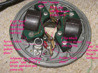 |
SF31 -
The various parts of the "points,"
along with the "adjuster", which
is used when setting the points "gap."
|
|
You can now install the new points base plate with
it's single retaining screw and place the new rocker
arm on it's pivot shaft: use the other cylinder's
points as a guide to make sure you have the rocker
arm placed correctly. Install the (2) little clips
for the rocker arm shaft. You can then install the
new condenser and secure the wire from the condenser,
the wire from the bottom of the coil (and the kill
switch wire, if you have one) under the little terminal
screw on the points base plate.
Replace the points and condenser for the other cylinder
and the magneto is now ready to be reinstalled on
the engine, but let's wait until we have the carb
work down before putting the mag back on. That will
give use a bit more room to work with.
One last comment before closing for this month:
you may have noticed (2) little red capsules that
resemble cyanide capsules that came with the tune-up
kit. Those are not to put you out of your misery if
you screw-up something. Now, you might actually want
to use them although I never have. More on the capsules
next time.
Later,
Max

click here for a
list of Columns by Max Wawrzyniak
|